 by Todd Bristol Jun 2, 2017
Welcome to The Perfect Storm!
In this series, we will look at the Not So Obvious scenarios where the “right” combination of “wrong” things happened, and the result produces a loss in reachability, connectivity, etc. After discussing the failure, we will go back and determine what happened (Why Did It Fail?). We will also look at how the failure may have been prevented or minimized using NetBrain.
Let’s get started!!
Network Overview: What’s the Scenario?
In this scenario, we find a section of the network can’t communicate with a cloud based resource during acceptance testing.
Here’s the network environment we’re working with:
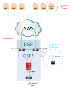
Figure 1: Data center connectivity to AWS Cloud
RT1 and RT2 each peer into an AWS environment via BGP, and each has a different Physical path into AWS. These two routers have an iBGP relationship with each other across the 172.16.110.0 network. In addition, RT1 and RT2 run OSPF on two separate networks: the 172.16.110.0 network, and on the 10.70.28.0 network. Traffic on the 10.70.28.0 network (from RT1 and RT2) passes thru a firewall to get to a third OSPF Neighbor, RT3, which handles the Layer-3 routing/traffic for Data Center Subnets.
Failure Overview: Right Combination of the Wrong Things
For the past two evenings @11pm, a network management station on the 10.17.1.0 network runs performance tests towards an AWS host in the 10.192.16.0 network. The tests normally take 10-15 minutes to complete. On the third and final night of testing, the tests are delayed until @2am, in the middle of the AWS Circuit provider’s maintenance window (where maintenance is being performed on Physical Path A). Although no connectivity related problems were reported from any of the hosts in the Data Center, the performance tests run from the network management station failed. Why Did It Fail?
TROUBLESHOOTING METHODOLOGY
Let’s take a closer look at the environment, see what changed, and determine how those changes influenced the environment. So, what happened on the First and Second nights of testing? Let’s take a look:
- The Network Management Station attempted to reach a host in the AWS behind VPC F.
- Traffic from the station was sent to the HSRP Primary Gateway, which was RT1.
- RT1 had a BGP installed route to 192.16.0, which it learned from the AWS BGP peer (VGW) associated with VPC F.
- Traffic was forwarded towards the peer.
- Return traffic from the VPC host was forwarded out of that VPC towards RT1, as RT1 had advertised the 10.17.1.0 network towards AWS (both RT1 and RT2 advertised these routes, however RT2 had Prepended the path in its advertisement).
- RT1 directed the incoming traffic towards it’s directly connected interface to 17.1.0. where the station resides.
- Success!!
NOW, look specifically at what happened on the Third Night!! First, we can start by identifying what we know: The ISP Primary Connection was taken down.
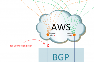
Figure 2: Showcasing the problem, i.e., taking down the ISP primary connection
Next, let’s talk about how the break in the circuit affected routing tables… specifically on RT1. Prior to the ISP maintenance window, RT1 had an eBGP route in its table from the eBGP peer of VPC F.
RT1#sh ip route 10.192.16.0
Routing entry for 10.192.16.0/24
Known via “bgp 65535”, distance 20, metric 0
Tag 7224, type external
Redistributing via ospf 1
Advertised by ospf 1 subnets route-map DENY-SUMM
Last update from 192.168.8.6 00:04:10 ago
Routing Descriptor Blocks:
* 192.168.8.6, from 192.168.8.6, 00:04:10 ago
Route metric is 0, traffic share count is 1
AS Hops 1
Route tag 7224
MPLS label: none
RT1#
After the circuit break however, RT1s routing table looks very different. RT1s table now has two entries for the 10.192.16.0 network, one towards RT2 on its GigabitEthernet 0/3 interface, and another towards RT2 on its GigabitEthernet 0/1 interface.
RT1#sh ip route 10.192.16.0
Routing entry for 10.192.16.0/24
Known via “ospf 1”, distance 110, metric 400
Tag 7224, type extern 2, forward metric 1
Redistributing via bgp 65535
Last update from 10.170.28.12 on GigabitEthernet0/1, 00:00:37 ago
Routing Descriptor Blocks:
* 172.16.110.12, from 10.70.28.12, 00:00:41 ago, via GigabitEthernet0/3
Route metric is 400, traffic share count is 1
Route tag 7224
10.70.28.12, from 10.70.28.12, 00:00:37 ago, via GigabitEthernet0/1
Route metric is 400, traffic share count is 1
Route tag 7224
VIRL-PHX-AWS-RT1#
But how would this cause a failure? How would an extra valid route cause the management station’s connection to VPC F to fail? To understand this, look at how traffic flows between VPC F and the Management subnet. Inbound traffic flows from VPC F, into R2 (the only available path), then down to the management subnet.
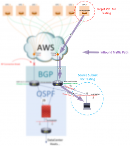
Figure 3: Understanding the inbound traffic flows
Outbound traffic takes a different path. This outbound path is initially dictated by the HSRP active member for the 10.17.1.0 subnet. It’s still set to RT1. Although traffic is now flowing outbound via RT2, RT1 remains the active router (default gateway) for the 10.17.1.0 subnet. With this in mind, follow the outbound flow below:
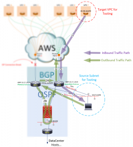
Figure 4: Understanding the outbound traffic flows
We can see the first path going to the default gateway (represented by RT1), but there are two equal hops represented on the second path! One to RT2 via the 172.16.110.0 network, and one to RT2 via the 10.70.28.0 network. With two equal Layer3 routes to RT2 available, RT1 will load balance, sending some of the traffic across the Firewall (2B) path. The Firewall will see an incomplete conversation and call out “Asymmetric Routing”, and break it.
ROOT CAUSE ANALYSIS
Now that we have a better understanding of what happened, it may be a good time to ask yourself, “How could I have seen this coming?” What questions should I be asking myself to better prepare for situations like this, and what tools will provide greater visibility into my network Infrastructure Underlay/Overlay? How do I become a better “network troubleshooter” and not just a “shooter”?
HOW NETBRAIN COULD HAVE HELPED
In the example above, the problem was identified as we mapped out the traffic path. Below I used NetBrain to graphically represent a traffic path by asking the routers how to get from the source (in this case, I used RT1…) to the destination:
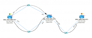
Figure 5: Create the traffic path using NetBrain
Below, NetBrain presents us with the actual pre/post Maintenance data from RT1s routing tables, representing the actual “decision making” data for the traffic paths we looked at above.
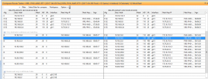
Figure 6: The routing table of Router 1 used to determine the traffic paths
And finally, we see (by using NetBrain to compare the pre and post maintenance BGP Neighbor states of RT1) BGP a Peer state that is the root of all of the events in this scenario… Idle (or any other non-established states) vs. Established states between RT1s BGP Neighbors.
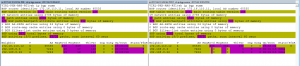
Figure 7: Comparing the “before” and “after” configurations
Using NetBrain together with VIRL on Packet is an unbeatable combination for simulating and monitoring/recording network performance and characteristics in Real Time, using Real “Production Like” buildouts, in a way that can be easily documented and transferred (configurations, monitoring, etc.) into a production environment.
To learn more about NetBrain, visit https://www.netbraintech.com/platform/