Creating MPLS Clouds
Generally, geographically dispersed networks are connected through the MPLS VPN network of an Internet Service Provider (ISP). The system introduces a concept called MPLS Cloud to simulate the MPLS functions by following the rules of forwarding labeled packets. In the system, MPLS Clouds are taken as devices and have virtual routing tables (VRT) to calculate A-B paths across MPLS.
Here is a sample of MPLS VPN network. It includes the following types of elements:

▪Customer Edge (CE) — routers at the customer premises that is connected to the provider edge of a service provider IP/MPLS network. CE peers with the provider edge (PE) and exchanges routes with the corresponding VRF inside the provider edge (PE).
▪Provider Edge (PE) — routers in the provider's network that is connected to the customer edge (CE) routers located at customer sites. PE routers support VPN and MPLS label functionality. Within a single VPN, pairs of PE routers are connected through a virtual tunnel, typically a label-switched path (LSP).
▪Provider (P) — provider routers within the core of the provider's network are not connected to any routers at a customer site but are part of the tunnel between pairs of PE routers. Provider routers support LSP functionality as part of the tunnel support, but do not support VPN functionality.
Note: Only the domain admin, power users, or users with the Device Management privilege can add, edit, and delete an MPLS Cloud.
Adding an MPLS Cloud
1.Log into Domain Management page.
2.In the Domain Management page, select Operations > Domain Manager from the quick access toolbar.
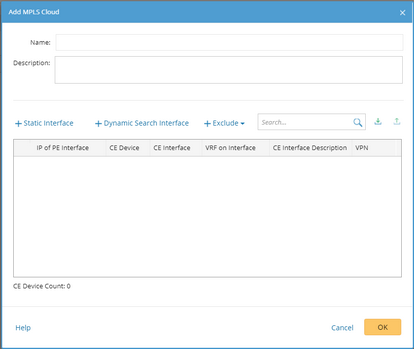
3.In the Domain Manager, select MPLS Cloud in the left pane and click Add.

4.In the Add MPLS Cloud dialog box, enter the name and description, and add CE devices to this MPLS Cloud by either of the following ways:
1)Select Dynamic Search Interface. 2)In the pop-up dialog, enter the BGP AS (Autonomous System) number and VRF (virtual routing and forwarding) name. Tip: VRF is used to establish the correct connections if some devices have duplicated IP addresses. Use a semicolon (;) to separate multiple items. 3)(Optional) To exclude specific devices from the search result, you can define criteria to filter them out. 4)Click Search. Tip: To automatically synchronize the list of CE interfaces with your live network, you can select the Auto update dynamic CE list check box. Then the CE list will be auto-updated when a discovery or benchmark task is executed. 5)Review the search result, click OK. |
|---|
1)Click Static Interface. 2)In the pop-up dialog, specify the properties of the CE device. a)Select the CE interface connected to the PE device. b)Select the routing protocol configured between the CE and PE interfaces. c)Input the IP address of the PE interface. d)Input the VPN (if available) that the CE device belongs to. When calculating MPLS VRT, the system saves the route entries that belong to the same VPN into one VRT, which ensures the accuracy of A/B path across MPLS Cloud from being affected by other unexpected VRFs in one VPN. Tip: The devices that meet all of the following conditions will be added to the CE list: - The devices not only configured with EBGP Neighbor but also pointing to the defined AS number. - The non-loopback interface in the same network segment with EBGP Neighbor IP configured on the device. - The neighbor IP of CE devices does not exist in the domain. 3) Click OK. |
|---|
Tip: To exclude specific interfaces or devices from the CE list, click Exclude and make settings. The priority of items in different categories is as follows:
- Manually excluded items have higher priority than those via dynamic search.
- Manually excluded items have the same priority with manually added ones. The latest update will be used.
5.Click OK. A confirmation dialog will prompt to ask you whether to rebuild IPv4 L3 topology or not. Make your selection based on needs.
Generating Virtual Routing Table
To make the MPLS Cloud have routes to the CE devices when calculating an MPLS VPN path, you need to generate a VRT.
The logic of calculating a VRT is as follows:
▪Collect BGP advertised routes to MPLS Cloud from CE devices.
▪MPLS Cloud builds its route tables based on routes advertised from CE devices and takes its connected CE interface as the next hop.
To generate a VRT for an MPLS Cloud, complete the following steps:
1.Point to the target MPLS Cloud and click the  icon to select Generate Virtual Routing Table.
2.In the pop-up dialog, select a data source to use the cached route table of the MPLS Cloud for calculation.
Tip: To automatically update the global VRT in the Current Baseline, select the Auto update global virtual route table check box.
3.Click Submit.
Tip: The global virtual route table can be updated in a Benchmark task. See Benchmark Task Settings for more details.
Path Calculation Logic for MPLS Cloud
An MPLS Cloud has its virtual routing table and interfaces, which enables path calculation across MPLS.
▪VRT is calculated based on benchmark data (including BGP advertised-route tables). For the devices which do not support the BGP advertised–route command, the route tables are required instead.
▪For the BGP advertised-routes, the system compares AS_path, original codes and metric (MED) in sequence to generate MPLS VRT. For others, the system only compares the metric.
Further operations:
1.Point to the target MPLS Cloud entry and click the 2.In the pop-up dialog, click Export. Tip: To change the VPN name for this MPLS Cloud, you can make changes in the exported file and then import it into the system. See the Example to download the correct template. |
1.Point to the target MPLS Cloud entry and click the 2.In the pop-up dialog, select a data source and then select a VRF to view the VRT of the MPLS Cloud. |
See also:
▪Context Menu in Domain Manager


