The Basic Output uses built-in functions to analyze and display table data, such as highlight devices with particular configurations on a map, draw devices on a map, create an alert when a predefined condition was met, create CSV report, set device properties or modify device queue. You can define the basic output without writing any scripts.
Defining Basic Output
1.Click the Basic Output node in the Qapp Editor.
2.Specify the execution logic. By default, the Qapp will automatically select an execution logic according to table type.
▪Execute by rows — execute the basic output node by table rows. For interface-level data or multiple-instance data, this option is selected.
▪Execute once — execute the basic output only once. For single-instance data or device-level data in an attribute table, this option is selected.
Tip: By default, the Qapp will automatically select an execution logic according to table data type and keep it as default.
3.Create conditions for consequent actions.
1)Click New Conditions.
2)In the Define Condition dialog, select the variable name (such as $mtu) and operator from the drop-down lists, then enter the value.
3)Repeat step 2) to add more conditions. You can use a Boolean expression to set relation between the added conditions, such as A and B, and A or B.
Note: The system creates a condition by default, whose condition is True. If multiple conditions are created, the default condition is only executed when all other conditions are not met.
4.Define Actions. Click the  icon on the Output node, choose a condition and select an action from the Action Node drop-down menu.
Generate alerts when predefined conditions are met. There are two types of alerts:
1)Select the Device Alert check box. 2)Select the device variable ($_device by default) from the Select Device drop-down menu. 3)Enter the alert name. 4)Select the alert level and enter the alert content. |
1)Select the Interface Alert check box. 2)Select the device variable ($_device by default) from the Select Device drop-down menu and select the interface variable. 3)Enter the alert name. 4)Select the alert level and enter the alert content. |
See also: Defining Alert in monitor output.
|
Print customized messages when predefined conditions are met.
1)Enter a name for the message node. By default, the name is Message1. 2)Enter a description of the node in the Description field. 3)Select the message level and enter the message. |
Highlight map refers to highlight the devices (including neighbor devices) or interfaces on the map.
There are three types of highlights:
By default, the Highlight Device check box is selected.
▪Device — select the device column from the previous table nodes.
If the previous table is Device Data Table, the device column will be auto-identified and cannot be modified. ▪Legend — enter the text for the color legend on the map. ▪Advanced — select the color and schema used to highlight the device. Tip: The Highlight Schema only works when you run multiple highlight Qapps. By default, Append is checked, which means that one highlight Qapp will append its color over the previous one.
|
Select the Highlight Interface check box and define the settings as follows:
▪Device — select the device column from the previous table nodes.
If the previous table is Device Data Table, the device column will be auto-identified and cannot be modified. ▪Interface — select the interface variable from the drop-down list. ▪Legend — enter the text for the color legend on the map. ▪Advanced — define line color, style, width and highlight schema. Tip: The Highlight Schema only works when you run multiple highlight Qapps. By default, Append is checked, which means that one highlight Qapp will append its color over its previous one.
|
Select the Highlight Neighbor check box and define the settings as follows:
▪Source Device — select the source device column from the previous table nodes.
If the previous table is Device Data Table, the device column will be auto-identified and cannot be modified. ▪Source Text — enter the text for the link on the source device side. ▪Destination Device — select the destination device column from the previous table nodes. ▪Destination Text — enter the text for the link on the destination device side. ▪Legend — enter the text for the color legend on the map. ▪Advanced — define line color, style, width, and arrow. |
|
Draw note refers to annotate the notes on the map, devices or interfaces and it is only applicable to the interfaces or devices that are visible on a map. There are three types of notes:
By default, the Map Note check box is selected.
▪Title — enter the title the note. ▪Content — enter the content for the note. You can invoke variables by entering $. ▪Advanced — define the following parameters in the Advanced dialog box.
|
|
|
Font Size
|
Specify the font size. The default value is 14.
|
Align
|
Specify the alignment direction. The default option is Left.
|
Forecolor
|
Specify the forecolor for the note box.
|
Background Color
|
Specify the background for the note box.
|
Border Color
|
Specify the border color for the note box.
|
Note Type
|
Specify how to display new map notes for recurring execution.
▪Append — retain the existing notes and append new notes behind. ▪Overwrite — remove the existing notes and display the new notes only. ▪History — retain the first note only (remove others) and append new notes behind. |
Note View
|
Select whether to expand or collapse the note on the map.
|
|
Select the Device Note check box and define the settings as follows:
▪Device — select the device column from the previous table nodes.
If the previous table is Device Data Table, the device column will be auto-identified and cannot be modified. ▪Title — enter the title for the note. You can invoke variables by entering $. ▪Content — enter the content for the note. You can invoke variables by entering $. ▪Advanced — you can refer to the Advanced settings in the Map note to define more settings. Note: The Auto Draw Device in the Advanced settings means that the Qapp will first draw the devices on a map and then draw notes on the devices.
|
Select the Interface Note check box and define the settings as follows:
▪Device — select the device column from the previous table nodes.
If the previous table is Device Data Table, the device column will be auto-identified and cannot be modified. ▪Interface — select the interface variable from the drop-down list. ▪Title — enter the title for the note. ▪Content — enter the content for the note. You can invoke variables by entering $. ▪Advanced — you can refer to the Advanced settings in the Map note to define more settings. Note: The Auto Draw Interface in the Advanced settings means that the Qapp will first draw the interfaces on a map and then draw notes on the Interface. Therefore, if the target interfaces are not visible on a map, you need to select this check box.
|
|
Draw Device refers to diagram devices, interfaces or hops on the map. Click the Draw Device node and configure the settings.
1)Enter the name and description. 2)Select the check box to draw devices or interfaces based on your needs.
By default, the Draw Device check box is selected.
▪Device — select the device column from the previous table nodes.
If the previous table is Device Data Table, the device column will be auto-identified and cannot be modified. ▪Topology Type — select the topology type based on your actual device layer. ▪Auto Link — select whether to enable the auto link function to the devices on the map. |
Select the Draw Interface check box and the settings are displayed as follows:
▪Device — select the device column from the previous table nodes.
If the previous table is Device Data Table, the device column will be auto-identified and cannot be modified. ▪Interface — select the interface variable from the drop-down list. ▪Interface Type — select an interface type, such as IPv4 or IPv6 interface. |
Select the Draw Hop check box and define the settings as follows:
▪Source Device — select the source device column from the previous table nodes.
If the previous table is Device Data Table, the device column will be auto-identified and cannot be modified. ▪Destination Device — select the destination device column from the previous table nodes. ▪Annotation — enter the text to be displayed on the link. ▪Advanced — define line color, style, and width. |
|
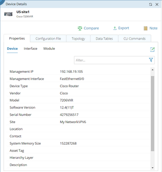
Device Property refers to configure the attributes for devices, interfaces or modules in the Properties tab of the Device Details pane.
1)Select the Interface Property check box. 2)Select device from the previous table nodes.
If the previous table is Device Data Table, the device column will be auto-identified and cannot be modified. 3)Select the interface variable and interface type. 4)Click Add and select your interested interface properties. |
Export Report refers to export the variables to a table file (both the .csv and .xlsx formats are supported).
Note: The CSV Export node is only available when the Basic Output node follows after a Global Data Table.
Click the CSV Export node and configure the settings:
1)Enter the node name and description. 2)Select the variables that you want to export from the Export Variables drop-down menu. 3)Enter the file name of the exported report. 4)Configure the Advanced option if Loop by table setting is enabled. By default, the Multiple files option is selected, indicating that if the Loop by table setting is enabled, then each loop will be exported in an individual .csv file.
To merge them into one .csv file with multiple spreadsheets, select the Append to one file option. |


