Topology Type
The following table introduces the built-in topology types.
Topology Type |
Description |
Example |
|---|---|---|
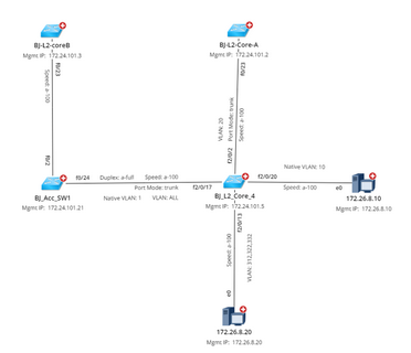
Layer 2 topology reflects the physical connections among devices. When building Layer 2 topology, the system learns how devices are connected by reading the data in NDP and MAC tables. To visualize L2 topology among devices on a map, physical interfaces and connections are parsed from device configuration files. For example, e0/0, f0/0, vlan10, and so on. Note: If the interfaces of a switch connect to multiple end systems, then a bus media will be used to connect the interface with the end system on a map. |
||
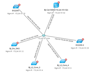
IPv4 Layer 3 topology reflects the connections among devices configured with IPv4 addresses. When building IPv4 Layer 3 topology, the system judges whether a device has IPv4 topology relationships with others by identifying whether their IPv4 addresses of interfaces are configured in the same subnet. To visualize IPv4 L3 topology among devices on a map, the IPv4 interfaces are created with the <interface name> <IPv4 address> format if the IPv4 addresses have been configured for the interfaces. For example, vlan 10 172.24.101.32/24. |
||
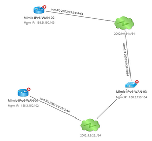
IPv6 Layer 3 topology reflects the connections among devices configured with IPv6 addresses. When building IPv6 Layer 3 topology, the system judges whether a device has IPv6 topology relationships with others by identifying whether their IPv6 addresses of interfaces are configured in the same subnet. To visualize IPv6 L3 topology among devices on a map, the IPv6 interfaces are created with the <interface name> <IPv6 address> format if the IPv6 addresses have been configured for the interfaces. For example, atm4/0 2002:9:9:34::4/64. Note: In the latest release, IPv6 Layer 3 topology only supports Cisco devices (Cisco Router, Cisco IOS Switch, Cisco IOS XR, Cisco Nexus Switch, Cisco ASA Firewall, Cisco PIX Firewall). |
||
L3 VPN Tunnel topology reflects the connections among devices configured with tunnel (GRE/IPsec VPN) technology. When building the L3 VPN Tunnel topology, the system judges whether a device has L3 VPN Tunnel topology relationships with others by identifying the tunnel peers. To visualize L3 VPN Tunnel topology among devices on a map, the VPN interfaces are created in the following formats for VPN and GRE tunnels respectively: ▪IPsec VPN Tunnel: outside peer-IP <IPv4 address>. For example, outside peer-IP 172.27.129.114. ▪GRE Tunnel: tunnel name. For example, Tunnel0. |
||
Logic topology reflects the connections among network data configured with CISCO ACI and VMware vCenter technology. See Using Viusal Space to Visualize Your SDN Architecture for more details. |


