Network

Contents
Network pane is used to manage, organize and provides views for discovered network resources in a domain, which includes both SDN network devices and legacy network devices.

Viewing your Network Resources in Network Pane
1.Click Network in the taskbar.
2.In the Network pane, select a category and view. The system provides four built-in types of network and provides specific views for them:
▪Physical Network (Legacy Network) — provides three built-in views to organize legacy network devices:
oDevice Type — organizes and display devices based on their types, such as Router, L3 Switch, Firewall, and LAN Switch.
oRoute Protocol — organizes and display devices based on the route protocols, such as BGP, EIGRP, and OSPF.
oVirtualization — organizes and display virtualized devices based on their status and Parent/Child relation.

▪Cisco ACI — contains network resources in a Cisco ACI fabric and provide two built-in views to organize the ACI fabric:
oApplication Centric View — allows you to see different tenants and the applications deployed under each.
oNetwork Centric — allows you to see what devices are part of the SDN fabric and how they connect to the rest of the network.
▪ESXi — contains VMware network resources and provide two built-in views to organize VMware network:
oHosts and Clusters — hierarchically displays the data centers, ESXi hosts, resource pools and virtual machines under a vCenter.
oNetworking — displays vSwitches, port-groups and virtual machines and their topology.
▪NSX-V — organizes and displays the NSX-v network resources in the Network pane based on NSX components
Viewing Node Details of Physical Network
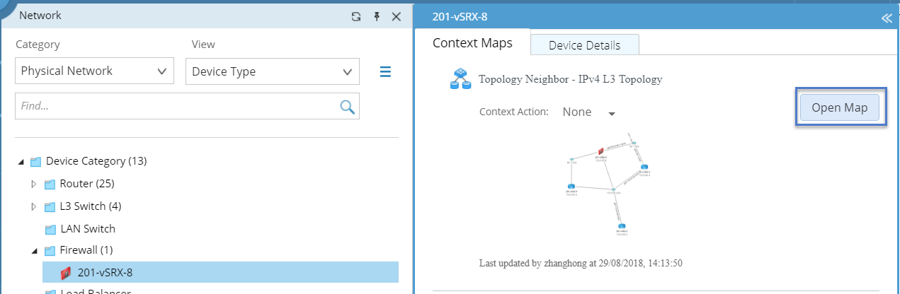
In the Network pane, you can drill down to view the details of a node and its context maps.
Example: View the node details and context maps of a firewall in a physical network.
1.Click Network in the taskbar.
2.In the Network pane, select Physical Network from the drop-down list and then select Device Type.
3.Expand the Firewall folder and select a specific firewall.
4.In the pop-up pane, click the Context Maps tab to view the context maps related to the device. For a firewall, the context maps display the topology with its L3 or L2 neighbors. Point to a context map, click Open Map to display the topology on a map.
Tip: You can select a device in the Network pane and directly drag the device to a map.
5.Click the Node Details tab to view its property and interface details of the firewall.
Customizing a Context
Context is corresponding to a specific network situation and you can customize contexts based on your needs and associate them with context maps and automation actions.
For how to define a context manually, see Using Context-Driven Automation for details.
The following takes VLAN for example to introduce the flow to create a context via script.
1.Go to Tenant Management page and then click the Platform Management tab.
2.On the Network tab, click the  icon of the Physical Network folder to select Add View.
3.Enter VLAN and press the Enter key to create the view.
4.Click the view and write scripts for the customized view.

The script for a view usually defines the following main components:
▪View name — the name of the view.
▪GDR property — the device or interface property that the view used to filter devices.
▪Visual Space Instance — a map associated with the view.
For more details about customizing a view and writing scripts, contact NetBrain Support Team for technical assistance.