Define Golden Intent
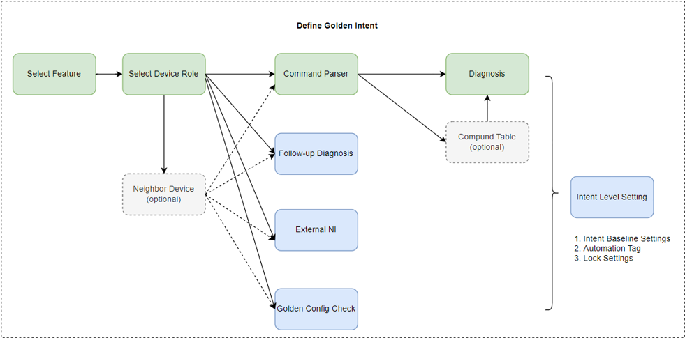
In Define mode, you can fully configure the golden intent by selecting a node, specifying the associated properties, and extending the configuration to another node. The extendable node types for each node are as follows:
- Start with Feature and Extend with Device Role
- Extend Device Role with Parser/Golden Config Check/ Neighbor Device
- Extend Golden Parser with Diagnosis
- Extend Golden Parser with Compound Table
- Extend More Actions
- Have the ability to select features and switch features.
- Display the properties related to the current feature.
- Display the device role information defined under the current feature.
- Device Role Node
- Each Device Role can be added to the flowchart as a stand-alone node and can be followed by different commands and diagnosis templates.
- Parser Variable
- Golden Config
- Neighbor Device Node
- Neighbor device node can be defined based on the related device node for subsequent checks
- Parser Variable
- Golden Config
- Used for diagnosis analysis of match pattern based on the selected golden rule.
- Automatically extended by selecting a specific variable on the device role node.
- Support configuration, CLI command, GDR, SNMP, and API.
- Diagnosis Node
- Compound Table Node
-
Support user to define diagnosis logic efficiently by 4 template:
comparing (with baseline/last/customized value/another variable). - Support merge, sub, append, and joint table nodes.
- Diagnosis Node
- Compound Table Node
- External Intent Node
- Follow-up Diagnosis
All nodes in the golden intent are summarized as follows:
| Node Type | Description | Extend Node Type | Can be added multiple times? |
|---|---|---|---|
| Feature |
|
|
No Note: It is unique and cannot be deleted. |
| Device Role Node |
|
|
No |
| Neighbor Device |
|
|
No |
| Golden Rule Node |
|
- | No |
| Command Parser Node |
|
|
Yes |
| Diagnosis Node |
|
- | Yes |
| Compound Table Node |
|
|
Yes |
| More Action |
|
- | - |
Start with Feature and Extend with Device Role
By default, an empty feature node is displayed. To proceed:
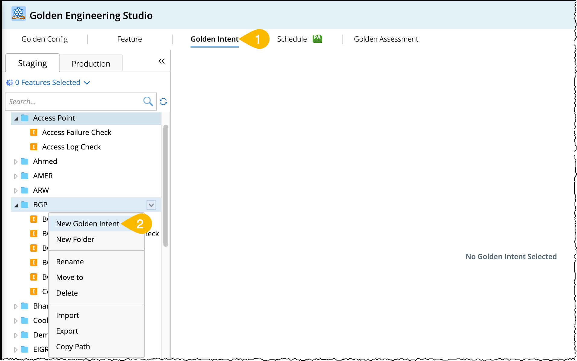
- Open the Golden Engineering Studio and go to Golden Intent > Staging.
- From the Golden Intent manager pane (left side pane), open the drop down menu of a folder and select New Golden Intent.
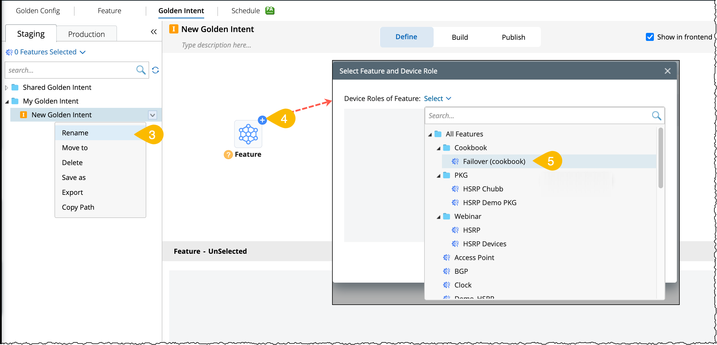
- Rename the default name of the golden intent as per your use case (eg: Monitor Failover State).
-
An empty feature node will appear in flowchart pane to begin the golden intent, click
 icon.
icon.
- Select a feature for the current empty node.
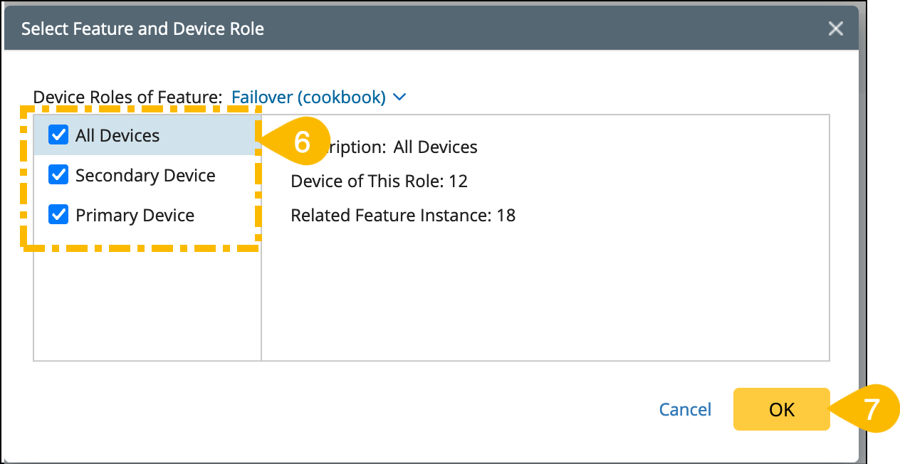
- Next, select the device roles defined in this feature and it will be applied to the current golden intent.
- Click OK to save and close the window.
Extend Device Role with Parser/Golden Config Check/ Neighbor Device
From the device role node, you can extend the following actions:

-
Parser
Choose the action type Parser to retrieve the command data and variables as follows:
- Select the Parser as the action type and the matched parsers will be listed.
-
Select a visual parser to retrieve the command data and variables for analysis.
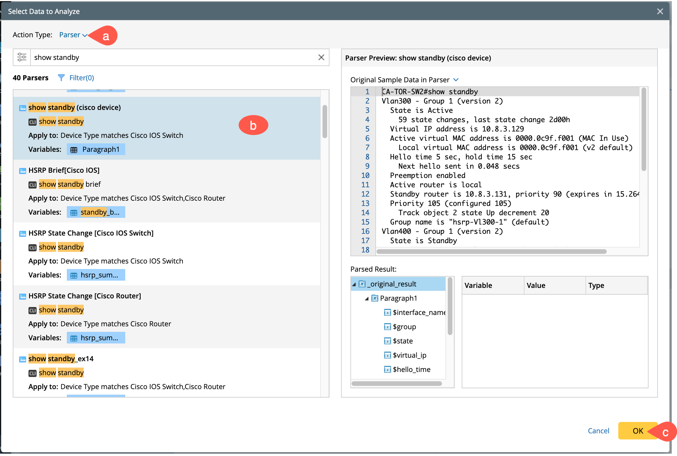
- Click OK to save and close the window.
-
You can define more settings of the data in the property pane, such as:
- Define the Macro Variable and assign value to it (if the macro variable exists).
- Customize the parser from Edit option.
-
Add a new column to the parser table with a customized variable using +Add Formula column.

In addition, all the parser variables will be available in the subsequent diagnosis nodes.
-
Golden Config Check
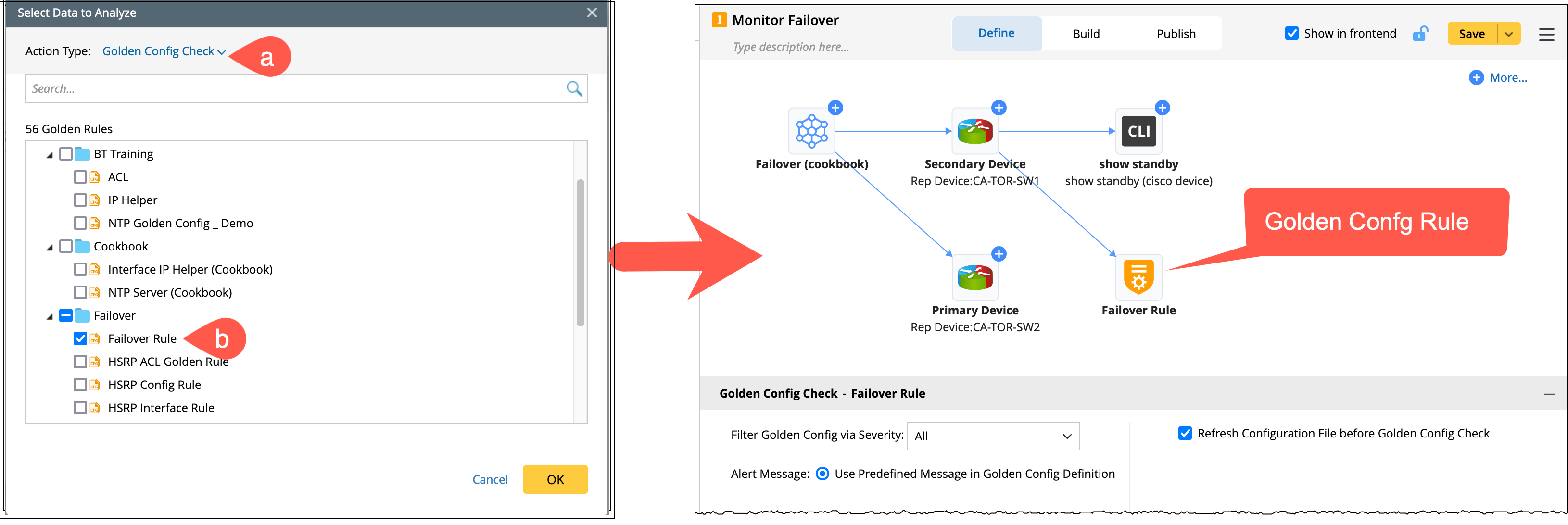
You can also extend the Golden Config Check node from the device role node.
- Select the action type as Golden Config Check.
-
Select a golden config rule to check, eg: Failover rule.
-
Neighbor Device
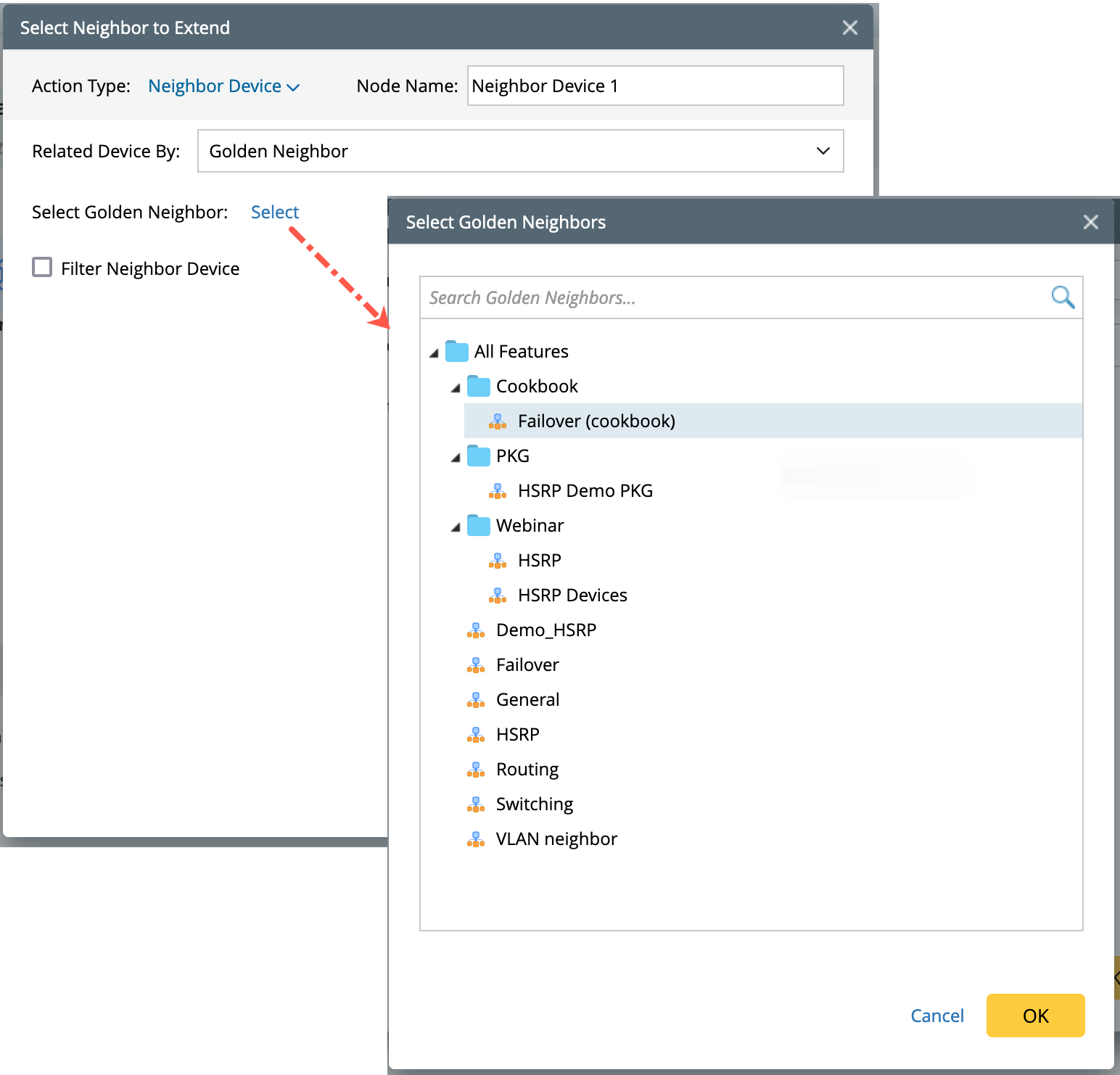
The device role defined in the feature are independent of each other and have no network relationship. You can extend neighbor devices from the device role node as follows:

- Select the action type as Neighbor Device.
-
Related Device by: Determine one of the following ways to extend the neighbor device:
- IPv4 L3 Neighbor/IPv6 L3 Neighbor/L2 Neighbor: You can extend all the neighbor devices based on topology and no additional configuration is required.
- Command Table: Refer to the table variables parsed from CLI commands. You can define formula columns for command table.
-
Golden Neighbor: This can be chosen to dynamically find neighbors depending on the structure of the golden table. Specify a golden neighbor table.
-
Filter Neighbor Device: Define the table column in the current device table match with Neighbor (when Golden Neighbor is selected).

-
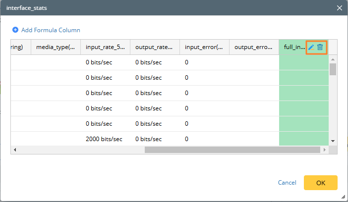
From the property pane, define Formula Columns in Command Table:
-
Click
 icon in the Neighbor Device node to view the current command table structure, it provides an entry to +Add Formula Column.
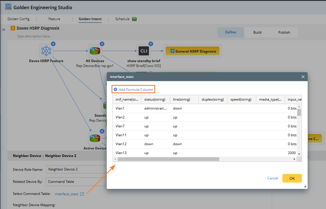
-
Click +Add Formula Column, a dialog Add Formula Column will pop up. The available variables are limited to the current table columns.

-
Click

Note:The newly added formula column can be deleted or edited, but it can be used only in the subsequent nodes.
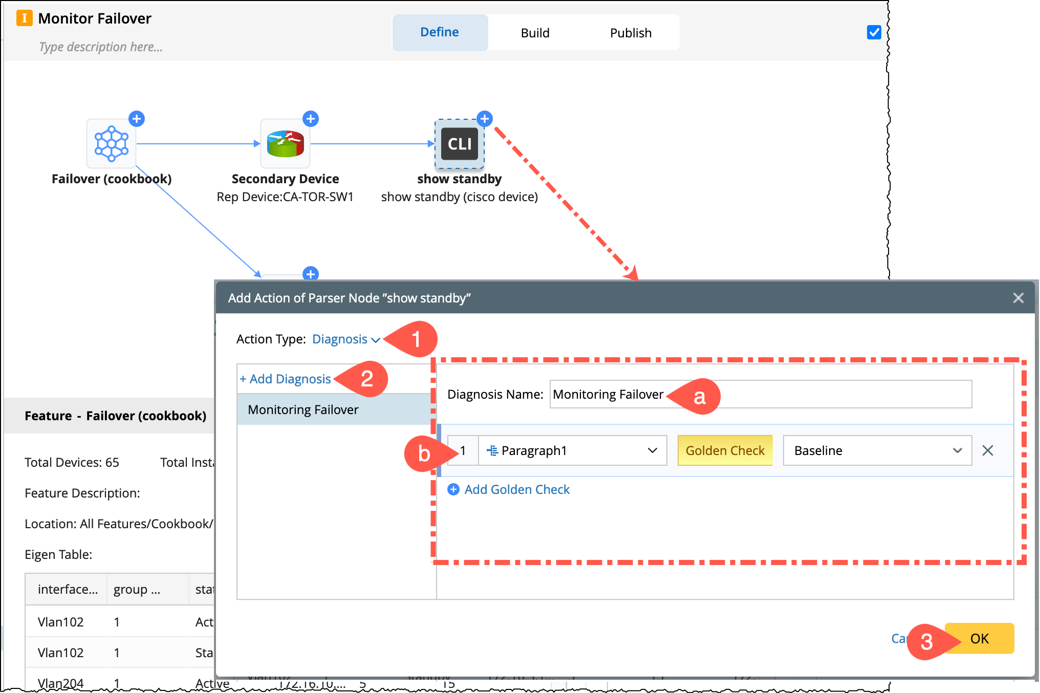
Extend Parser node with Diagnosis
Define diagnosis logic for the selected parser variables.
- Select Action Type Diagnosis.
-
Click Add Diagnosis.
- Rename the default diagnosis name as required, eg: Monitoring Failover.
-
Add Golden Check: Choose the variable (single variable or table variable) in the left column which is from the golden parser and in the right column select the action for the parser to do.
You can add multiple golden checks, each golden check will be regarded as an independent diagnosis.
- Click OK to save and close the window.
- In the property pane, define the diagnosis logic which is different for Single and Table Variables shown as below.
- Single Variable:
- Table Variable:
- Equals
- Does not equal
- Equals
- Does not equal
- Less than
- Greater than
- Less than or equals
- Greater than or equals
- In range
- Equals
- Does not equal
- Contains
- Does not contain
- Match Pattern
- Equals
- Does not equal
|
|
Note: You can add multiple diagnoses on the left, indicating that one or more nodes are followed. |


The details are listed in the below table:
| Diagnosis Type | Operator | Single Variable | Table Variable |
|---|---|---|---|
| Baseline |
|
Yes Normal Message |
Yes, Table Normal Message Summary Message Table-compare summary message |
| Last | |||
| Customized Value |
Number: String: Bool: |
Yes Normal Message |
Yes, Table Column Normal Message Summary Message Table-compare summary message |
|
Another Variable
|
Extend Parser node with Compound Table
You can also add the Compound Table nodes from the golden parser node. The compound table supports four types of nodes:

-
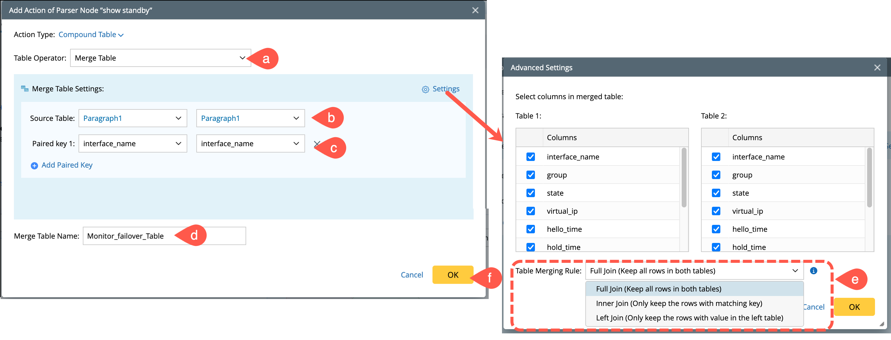
Merge Table
The merge table node merges multiple command tables using specific keys.

- Table Operator: Select Merge Table from the drop down menu.
-
Source Tables: Choose from multiple parsers under the same device role, or between the current and parent device roles. But they cannot be different feature device roles.
- The scope of the source table 1 is all table variables of the triggered parser or the compound table itself, and
-
The scope of the source table 2 can be all table variables of the triggered parser, as well as compound tables of all parsers under the current device role.
- Add paired keys: Define the paired keys from each table.
- Add a name to the merged table.
-
Go to Advanced Settings and define a rule to display the columns in merging table:
- Full Join: Returns all rows when there is a match in left (Table 1) or right (Table 2) table rows.
- Inner Join: Returns all rows that have matching values in both tables.
-
Left Join: Returns all rows from the left table (Table 1), and the matching rows from the right table (Table 2).
- Click OK to save and close the window.
-
Sub Table
This node will be used to obtain a subset table from the selected table by filtering with a condition. And the derived sub table will be used for subsequent diagnosis.
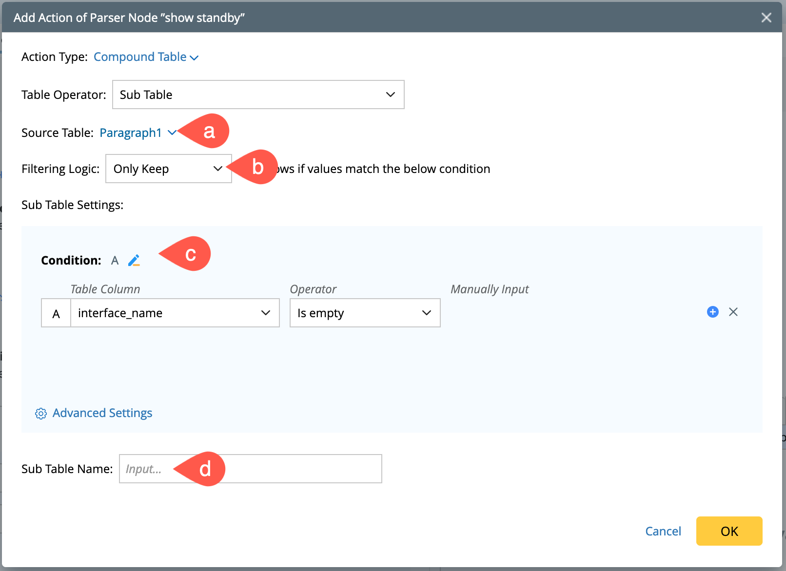
- Source Table: The scope is all table variables of the triggered parser, or the compound table itself.
- Filtering Logic: Select a logic either to keep certain rows or remove all rows when a value matches the defined Condition.
-
Condition: Define the logic using the boolean expression.
- Table Column: Select a column of the current source table.
- Manual Input: Enter the variables manually.
- Add a name to the sub table.
-
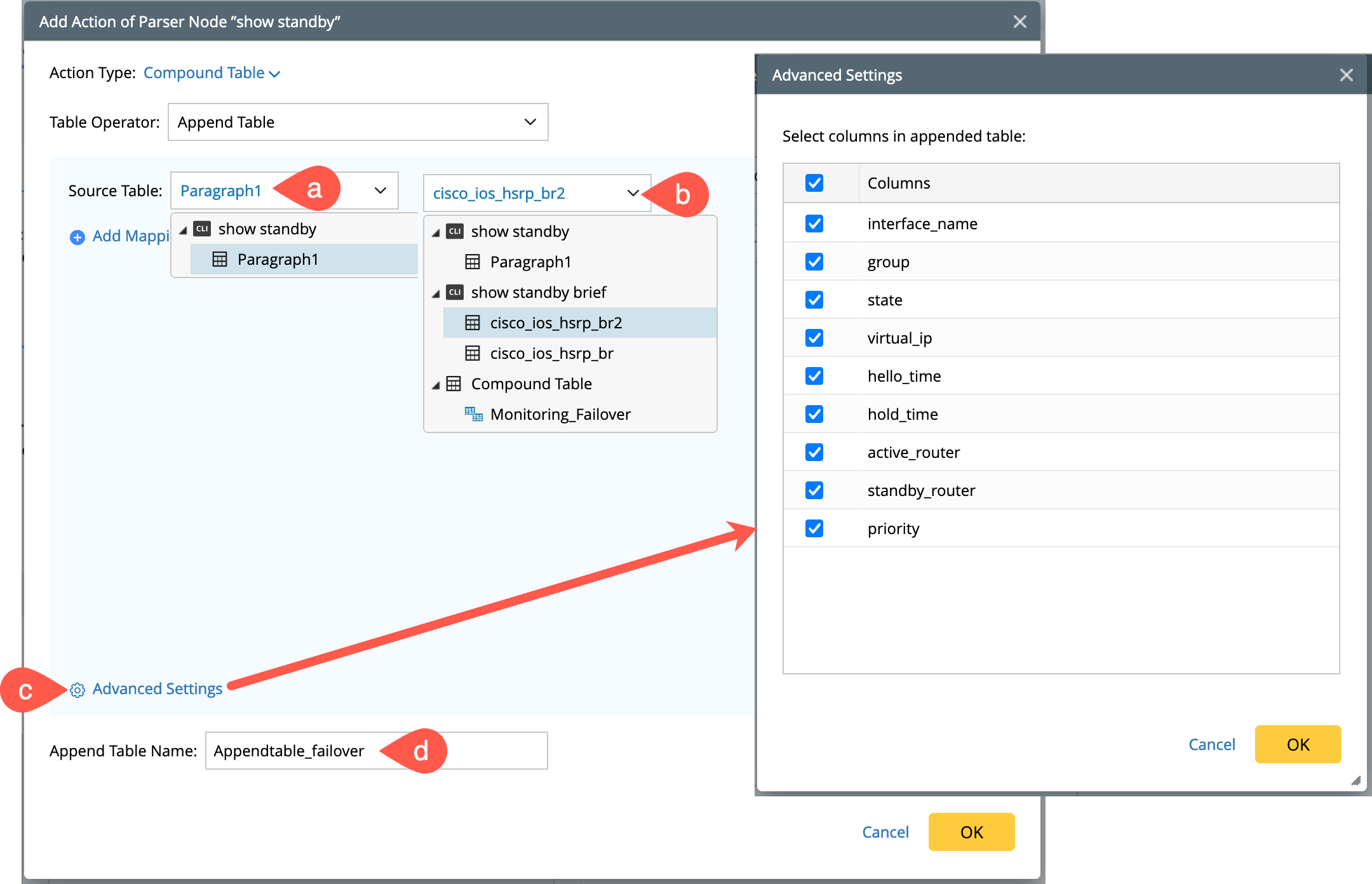
Append Table
This node is used to select two tables and merge their data according to the specified rules.
- Select Source Table 1: The scope is triggered parser, or the compound table itself.
- Select Source Table 2: The scope can be all variables of the triggered parser table or the compound tables under the current device role.
- (Optional) You can click Add Mappings to define more column mappings between the two source tables.
- Click Advanced Settings to select the columns to keep in the generated appended table.
- Add a name to the Append table.
-
Neighbor Join
The join table node is used to merge two parser tables and one global neighbor table based on the specified mapping rules. Merging can occur between multiple parsers under the same device role, or between the current device role and the parent device role, but not between different feature device roles.
Note: Neighbor Join is only supported for parsers extended by the neighbor device role. 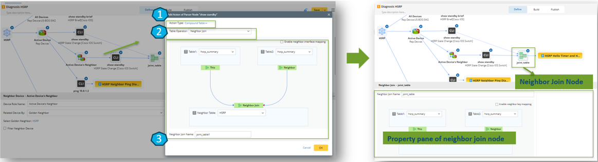
- Select the action type as a compound table.
- Select table operation type.
- Define the logic for neighbor join.
- Neighbor Table: The scope is all table variables of the triggered parser, or the compound table itself. In addition, the neighbor table extended by the current neighbor device node can also be used.
- Source Table1: The scope is all table variables of the triggered parser, or the compound table itself.
- Source Table2: The scope can be all table variables of the triggered parser, as well as the table variables and compound tables of all parsers under the device role to which the current parser belongs.

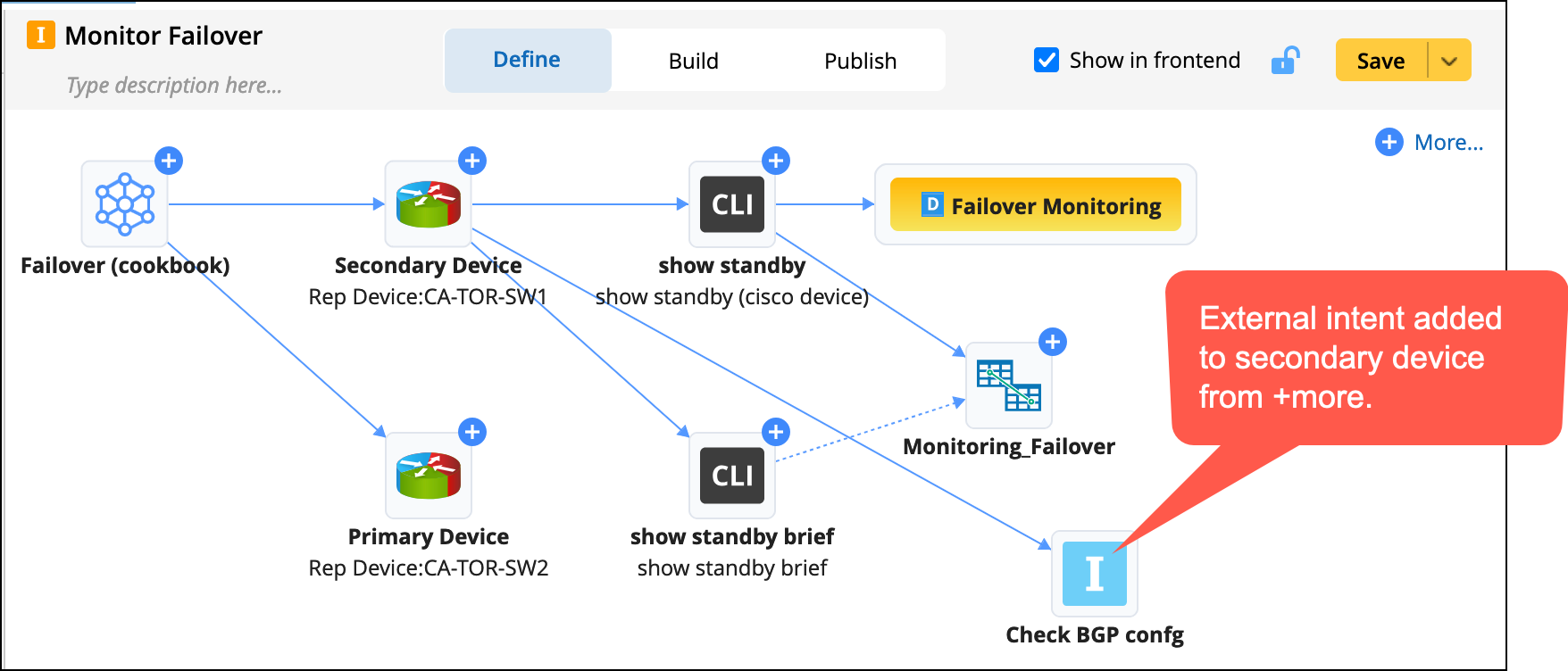
Extend More Actions
You can add an external intent or a follow-up diagnosis from  . Select an NIT and device role and the system will generate a device section and a device diagnosis for all devices in the selected device role.
-
Select External Intent / Follow-up Diagnosis from to open the configuring dialogue.
- Rename the node name as per use case.
- Select the Primary/Secondary device role to add the external intent.
- Select an Intent Template.
- Click OK to save and close the window.

If the selected NIT has macro variables, assign values to the macro variables. If you are assigning values using ADT, then set the device key for ADT.
