R12.1-JA-2025June05
Defining Topology Link Style
Topology Link Style defines the graphical display of topology links, such as line shapes, colors, and thickness. The system provides the following 11 built-in styles: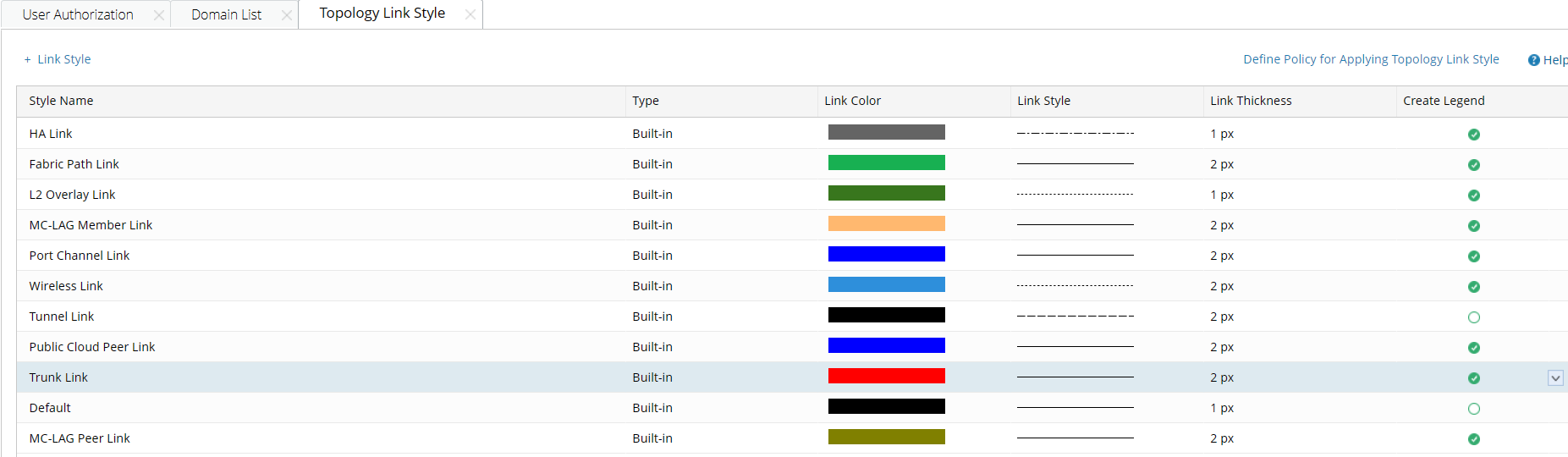
You can define a new topology link style for other network technologies:
- Log in to the Tenant Management page.
- On the Tenant Management page, select Topology Link Style from the start menu.
- Click + Link Style and define its information. Click OK.
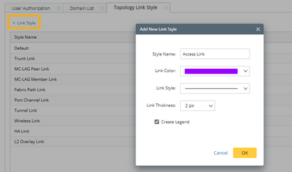

Tip: By default, the Create Legend check box is selected, which means a legend will be displayed on maps to represent the link style. - Click Define Policy for Applying Topology Link Style. On the Customized Policy tab, enter the scripts, and click OK.
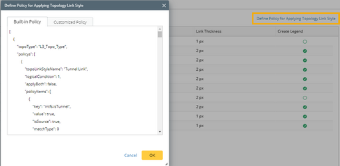
Tip: See Script Sample for more details. Contact NetBrain Support Team for assistance if you have questions about defining the policy. - View the display effects on a map.
Tip: End users can right-click the link on a map to change the link style.
Policy Script Example
The following is an example of the policy script to define how to apply a topology link style:
Code |
[ |
The following table lists the required parameters and their descriptions. The related properties are saved in the GDR.
| Parameter | Description |
| topoType | The topology type for a link style, such as L2_Topo_Type and L3_Topo_Type. |
| topoLinkStyleName | The unique name for a link style, which must be the same as you define. |
| logicalCondition | The operator among multiple conditions.
|
| applyBoth | The port that the link style applies to:
|
| key | The condition you want the port to match. |
| value | The value of the condition. |
| isSource | The port that is verified while matching the condition:
|
| matchType | Multiple values can be defined in one condition. The link style will be applied in the following situations:
|