10.1.15.12-06212024
Map Layer 2 Topology
Layer 2 topology links can be drawn on the same map page as layer 3 topology links by extending neighbors or Auto Link.

|
Note: Before mapping layer 2 topology, make sure you have scheduled the Basic System Benchmark task to build layer 2 topology. See Schedule Basic System Benchmark Task for more information. |
- Search for the target device by IP address or hostname in the search bar. See Search for Devices for details.
- Drag the device icon from the search result to the current map page. The device will be diagrammed on a map.
- Click the
 icon attached to the device to extend layer 2 neighbors.
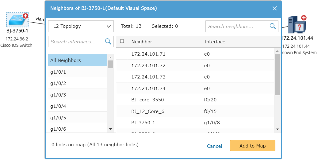
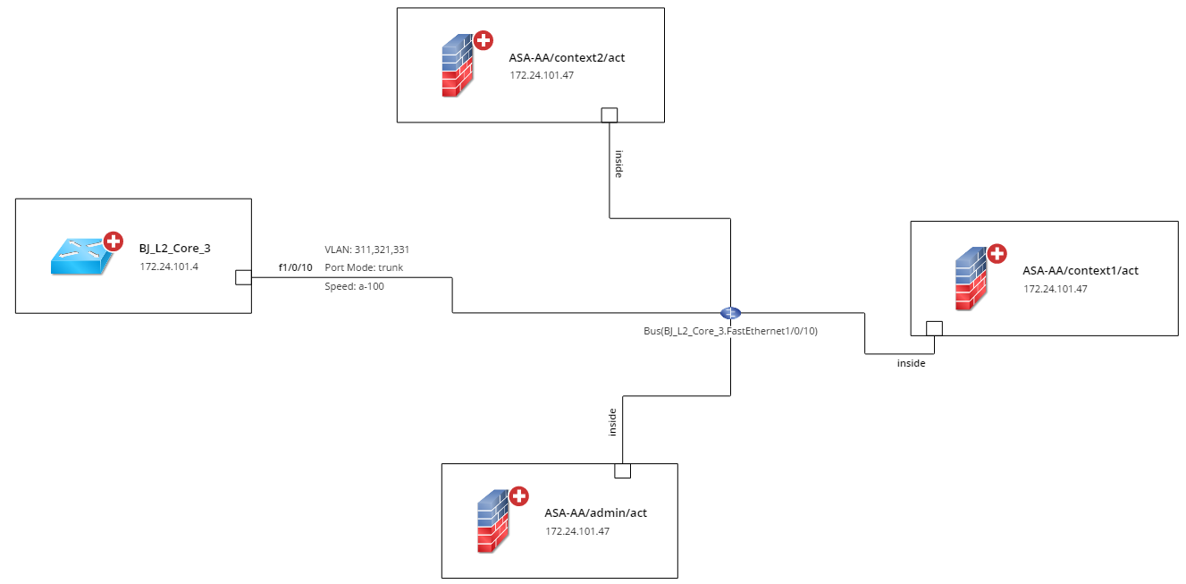
Tip: The bus icon  is a medium used to simulate a layer 2 port on a map when the port is connected with more than 2 ports or devices.
- To view the port-to-port connectivity among the devices, right-click any blank area of the Map and then select Change Device Style > Expanded Style.
 a
a
Tip: You can rotate the wheel button of your mouse forward to zoom in on the Map to view more detailed information.
Further operations:
- To switch between logical ports and physical ports in port channels, right-click the blank area and then select Port Channel > Show All logic Ports/Show All Physical Ports. To switch to a specific link, right-click the link.
- To view the summary information about a port, point to the target port. To create a note for the port information, click the
 icon.
icon. - To highlight VLAN on the Map, right-click the blank area to select Run Qapp from the drop-down menu, and then select the Highlight VLAN under the Highlighting category.
- To view the detailed interface information about a device, right-click the device and then select View Device Details. Click Interface under the Property tab.
See also: