Creating MPLS Clouds

Contents
Generally, geographically dispersed networks are connected through the MPLS VPN network of an Internet Service Provider (ISP). The system introduces a concept called MPLS Cloud to simulate the MPLS functions by following the rules of forwarding labeled packets. In the system, an MPLS Cloud is taken as a device and uses a virtual routing table to calculate A-B paths across the MPLS.
Here is a sample of MPLS VPN network. It includes the following types of elements:

▪Customer Edge (CE) — routers at the customer premises that is connected to the provider edge of a service provider IP/MPLS network. CE peers with the provider edge (PE) and exchanges routes with the corresponding VRF inside the provider edge (PE).
▪Provider Edge (PE) — routers in the provider's network that is connected to the customer edge (CE) routers located at customer sites. PE routers support VPN and MPLS label functionality. Within a single VPN, pairs of PE routers are connected through a virtual tunnel, typically a label-switched path (LSP).
▪Provider (P) — provider routers within the core of the provider's network are not connected to any routers at a customer site but are part of the tunnel between pairs of PE routers. Provider routers support LSP functionality as part of the tunnel support, but do not support VPN functionality.
Note: Only the domain admin, power users, or users with the Device Management privilege can add, edit, and delete an MPLS Cloud.
Adding an MPLS Cloud
1.Log in to the Domain Management page.
2.In the Domain Management page, click Fine Tune on the Start Page or select Operations > Fine Tune from the quick access toolbar.
3.On the Fine Tune tab, select Cloud Manager in the left pane and click Add in the right pane.
4.In the Cloud Definition dialog box, follow the steps below to define an MPLS Cloud.
1)Enter a name for the cloud.
2)Keep the default Cloud Type MPLS L3 VPN.
3)Enter a description of the MPLS cloud.
4)Add MPLS edge devices to the MPLS Cloud by either of the following ways:

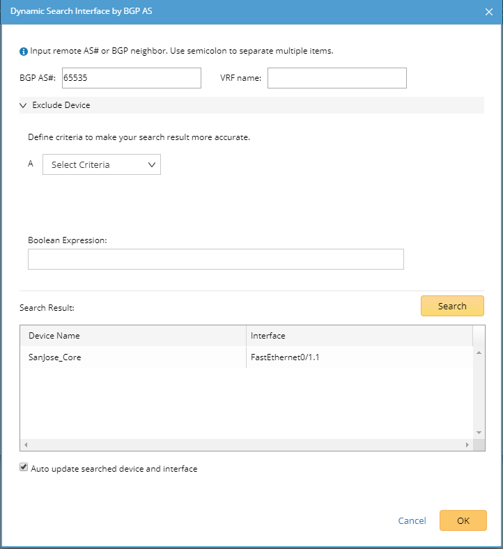
1)Click Dynamic Search Interface. 2)In the pop-up dialog, select By BGP AS (autonomous system) to add edge devices and interfaces based on BGP AS number and VRF. Tip: You can also select By Advanced Search in the pop-up dialog and use the Advanced Search function to find the edge devices and interfaces. 3)Enter BGP AS number and VRF name. Tip: VRF is used to establish the correct connections if some devices have duplicated IP addresses. You can enter multiple VRF names and use semicolons (;) to separate them. Interfaces that have the matched VRF names will be searched out. If you don't want to use the VRF name as a condition to filter interfaces, left it empty; if you want to search interfaces without VRF configured, enter 'global' (single quotes must be included). Tip: Through a specified BGP AS number, a device that meets all the following conditions will be added as a CE device: - The devices not only configured with EBGP Neighbor but also pointing to the defined AS number. - The non-loopback interface in the same network segment with EBGP Neighbor IP configured on the device. - The neighbor IP of CE devices does not exist in the domain. 4)Click Search. Tip: To exclude specific devices from the search results, you can define more filter criteria. Tip: To automatically synchronize the list of edge devices and interfaces with your live network, you can select the Auto update searched device and interface check box. 5)Review the search result, click OK. |
|---|
1)Click Static Interface. 2)In the pop-up dialog, specify the properties of the CE device. a)Click Browse to select the CE device. b)Select the interface of the CE device connected to the PE device. c)Enter the VRF name of the CE interface if it has been configured with a VRF. d)Enter the description of the CE interface. e)Enter the IP address of the PE interface that the CE interface connects to. f)Enter the name of the PE interface. The PE interface name can be any strings, and you can name it based on your needs. g)Enter a VPN value for the CE device. Note: Assign the same VPN value to those CE devices in different sites that have communications with each other. When the system builds a routing table for an MPLS cloud, CE devices with the same VPN value will be added to one virtual routing table. If the VPN field is left empty, the system will determine that all CE devices in an MPLS cloud communicate with each other. 3) Add more CE devices to the MPLS Cloud by following step 2. 4)Click OK. |
|---|

5.(Optional) Click Exclude to select CE devices or interfaces that you want to exclude from the MPLS cloud.
6.Click OK.
Building Topology and NCT Table for MPLS Cloud through a Benchmark
After creating an MPLS cloud, you need to build the topology and NCT table (a virtual routing table used for path calculation) via a benchmark task.
To build the topology and NCT table for an MPLS Cloud, complete the following steps:
1.Edit a benchmark task and go to the Additional Operations after Benchmark tab.
2.In the Update Cloud area, select the Recalculate MPLS NCT Tables option.
3.In the Build Topology area, select the IPv4 L3 topology option.
The system will build topology and NCTs for all MPLS clouds after the benchmark task is completed.
Calculating Paths across an MPLS Cloud
After building the NCT and topology, you can calculate paths across MPLS clouds. During the path calculation, the system looks up the virtual routing table to find the correct inbound and outbound traffic interfaces of the MPLS cloud.

Further operations:
1.Point to the target MPLS Cloud entry and click the 2.In the pop-up dialog, click the |

1.Point to the target MPLS Cloud entry and click the 2.In the pop-up dialog, select a data source and then select a virtual routing table from the NCT drop-down list to view. |
See also: