Mapping Layer 2 Topology

Contents
Layer 2 topology links can be drawn on the same map page with layer 3 topology links, by extending neighbors or auto link.
Note: Before mapping layer 2 topology, make sure that you have scheduled the Basic System Benchmark task to build layer 2 topology. See Scheduling Basic System Benchmark Task for more details.
1.Search for the target device by IP address or hostname in the search bar. See Searching for Devices for more details.
2.Drag the device icon from the search result to your NetworkBrain desktop. The device will be diagrammed on a map.
3.Click the  icon attached to the device to extend layer 2 neighbors as follows.

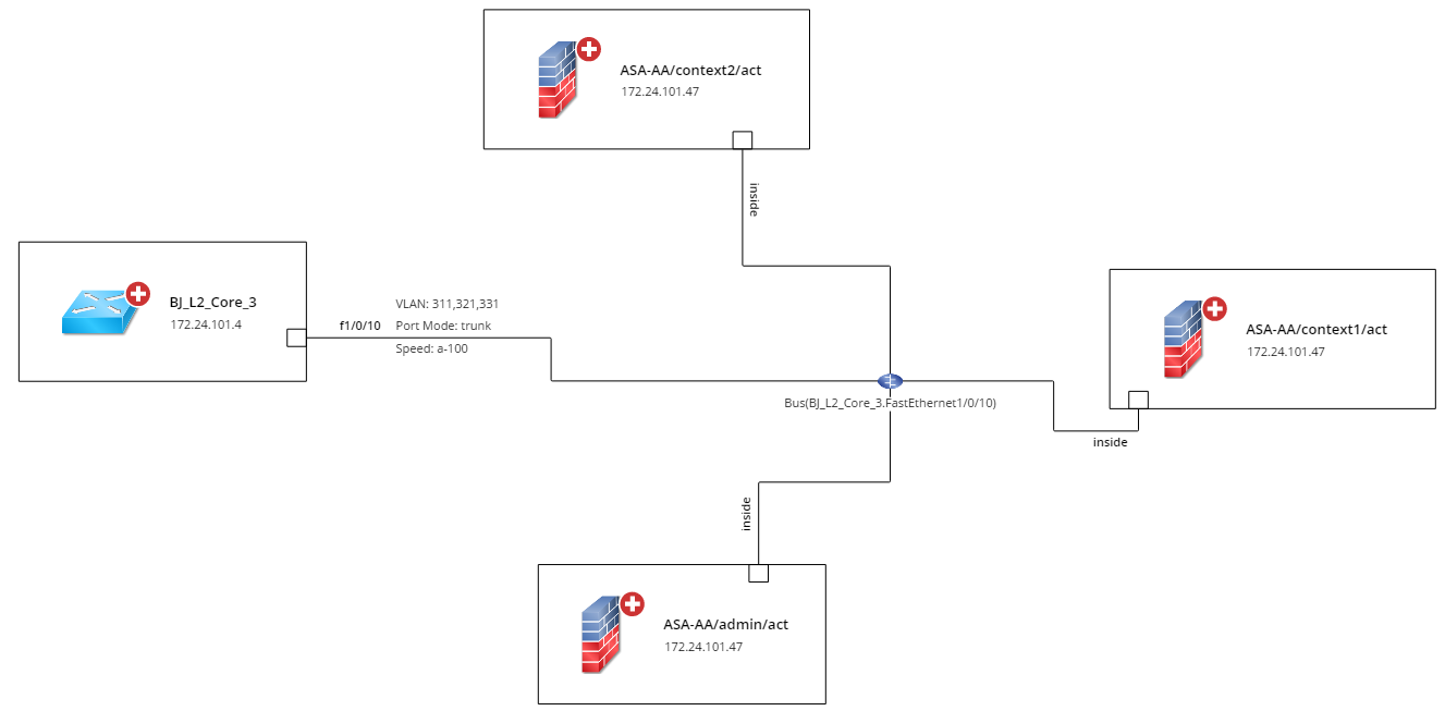
Tip: The bus icon  is a medium used to simulate a layer 2 port on a map when the port is connected with more than 2 ports or devices.
4.To view the port-to-port connectivity among the devices, right-click on any blank area of the map and then select Change Device Style > Expanded Style.
Tip: You can rotate the wheel button of your mouse forward to zoom in on the map to view more detailed information.
Further operations:
▪To switch between logical ports or physical ports in port channels, right-click the blank area and then select Port Channel > Show All logic Ports/Show All Physical Ports. To switch to a specific link, right-click the link.
▪To view the summary information about a port, point to it. To make a note for the port information, click the ![]() icon.
icon.
▪To highlight VLAN on the map, right-click the blank area to select Run Qapp from the drop-down menu, and then select the Highlight VLAN under the Highlighting category.
▪To view the detailed interface information about a device, right-click the device and then select View Device Details. Click Interface under the Property tab.
See also: