Understanding Network Structure of an ACI Fabric

Contents
In the Network pane, you can view the network structure of an ACI Fabric in the Network Centric\Tenant View.
1.In the Network pane, select Network Centric View > Tenant View.
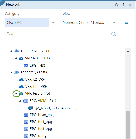
Tip: In the Network Centric View\Tenant View, ACI data model is organized in this order: Tenant > VRF > EPG (Endpoint Group) > Endpoint. You can view the following information of a tenant (or VRF) in the ACI fabric:
▪Tenants, VRFs, EPGs, and Endpoints.
▪Overlay topology of a tenant (or VRF) in the fabric.
▪Underlay topology of a tenant (or VRF) in the fabric.
2.Expand a tenant node to view the relationship of Tenant/VRF/EPG/EP.
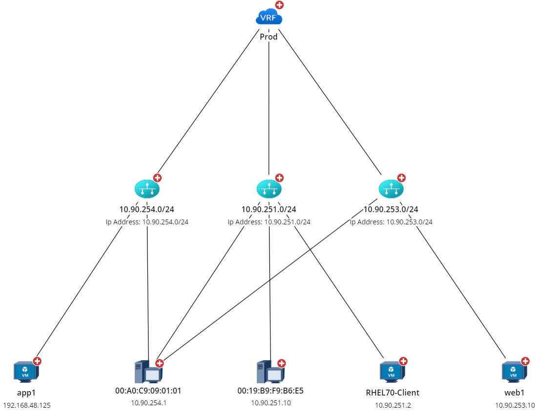
3.Click a VRF node, select Context Maps, and then select a map to view the corresponding structure of this VRF.
▪Overlay — represents the logic relationship among VRF > Subnet > Endpoint, including:
oThe connection of this VRF to an external network as well as the relevant external devices.
oThe mapping of Bridge Domain (in this VRF) to VLAN and subnet.
oEndpoints in an EPG.
The figure below displays the overlay topology of a VRF node.
▪Underlay — represents the physical resources occupied by a tenant, including:
oSpine and leaf switches that belong to this VRF.
oL3 Out and L2 Out switches in the VRF.
oAll endpoints in the VRF.
oConnectivity of these devices.
The figure below displays the underlay structure of a VRF node.
