Defining Flash Probe

Contents
There are different types of flash probes in the NetBrain system. Here we use the primary alert-based flash probe as an example to illustrate the basic procedures of defining flash probe:
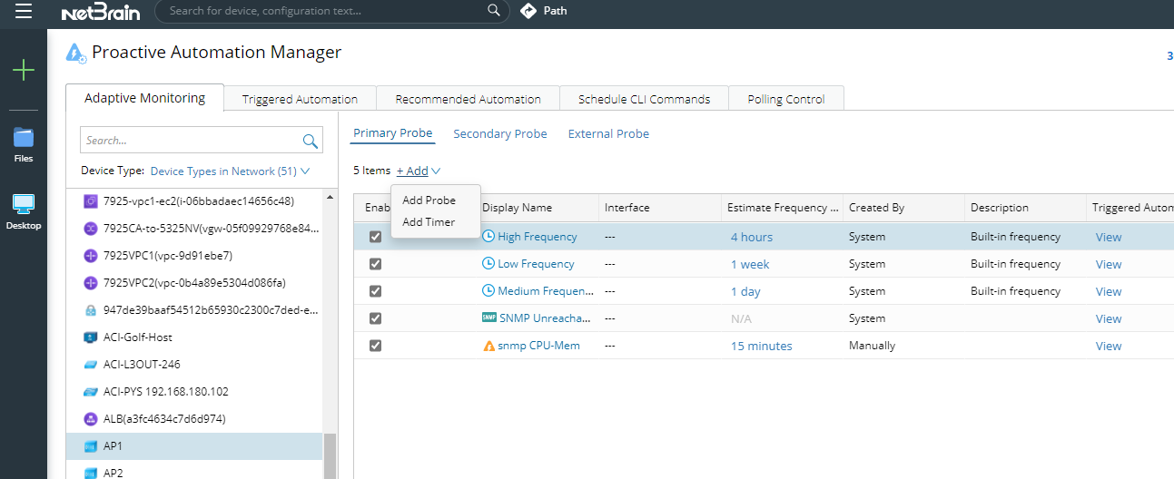
1.Click  on the task bar and select Proactive Automation Manager from the drop-down menu.
2.From the Adaptive Monitoring tab and on Primary Probe pane, select the target device and click +Add. From the drop-down list, select Add Probe.
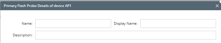
3.Define an Alert-based Flash Probe in the Primary Flash Probe Details of device window:
1)Define the basic information, such as the name, display name and description of the flash probe.
2)Configure the level setting.

•To capture device-level anomalies, such as CPU high, device config change, BGP neighbor flapping, select Device level.
•To capture interface-level anomalies, such as interface flapping, interface error increase, select Interface Level. Flash probe can be configured at multiple interfaces of the same device. In this case, the system will check the selected interfaces one by one. If anomaly exists in any of the selected interfaces, alert will be generated and respective NIs will be triggered.

3)To define the variables that need to be monitored, click +Add Variable to add variables.

•When the level is set at device level: Choose Add Device Variable from the drop-down menu. Search and locate the intended variable. Check it then click OK. Once a variable is added, you can also choose Add Compound Variable from the drop-down. menu.

•When the level is set at interface level: Select Add Device Variable or Add Interface Variable from the drop-down.Search and locate the intended variable. Check it then click OK. Once a variable is added, you can also choose Add Compound Variable from the drop-down.

Note: If a flash probe includes multiple interfaces, all the interfaces will use the same value for the parameter to retrieve the data.
•Compound variables are designed to perform bulk operations on multiple parser variables or use function calls to retrieve certain value. See Compound Variable for more details.
| Example: CRC_Increase_Count = $crc-GetLastValue($crc) In this example, compound variable is used to get the CRC error increase count.  |
| Example: BGP_Neighbor_Change_Count = abs(GetTableRowCount($bgp_nbrs)-GetLastRowCount($bgp_nbrs)) In this example, we use the statement above to get the bgp neighbor change count compared to the data retrieval of last time.  |
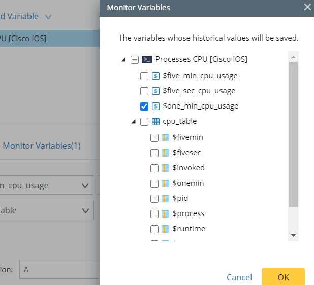
Monitoring Variables
You can select the parser variables deemed to be critical, instead of unselectively storing all historical parser variables. After selecting the specific variables, you can view them in the monitoring data view.
4)Define alert rules.
You can manually define the alert rules or simply leverage the golden baseline to trigger alerts.
•Manually define: Select rules manually to define the statement.

oCompare with last value: You can compare the current variable’s value with a number typed in or its previously retrieved value. To compare with its last value, simply use key word LastValue as the comparison object.
•Golden Baseline: Leverage the golden baseline of the current variable to determine whether the retrieved value violates the golden baseline for this device. If no static rule defined for the current parser variables, NetBrain will dynamically calculate the golden baseline for the current parser variable based on the historical value.

oloop table rows: The golden baseline checks alerts for the entire table. For granular control purposes, you can leverage loop table rows to check the value of specific column(s).

Note: You must select at least one table first and then select the desired column for the loop table rows to properly function.
Note: The system will loop each row to check whether the defined alert rule is matched. If any row matches the alert definition, an alert will be triggered and the system will stop checking for performance considerations.
5)Enter the alert message.
The alert message will be displayed in the decision tree and can be sent via email for notification purposes. In the alert message field, you can type $ to reference the variables defined in the alert rule statement.

Note: Not all defined variables can be referenced in the alert message field. In this version, table variables and compound variables used in alert rule definition cannot be referenced.
Apply the Primary Flash Probe to Other Devices
As mentioned above, the flash probe is created on a single device, however, it can be bulk applied to other devices.

The system will check whether the selected devices are valid for bulk application according to the logic below:
•The parser of existing flash probe can also be applied to the target devices. For example, if you use Cisco BGP Neighbor for the existing flash probe definition, you can apply the probe to other Cisco devices; or if the existing flash probe uses SNMP public MIB to get the device interface status, you can apply this flash probe to any other devices since the parser can be applied to all device types.
•If the same flash probe is already configured on other devices, you can decide to overwrite all duplicate flash probes or keep them to suit your specific needs.
Enable/Disable the Primary Flash Probe on Other Devices
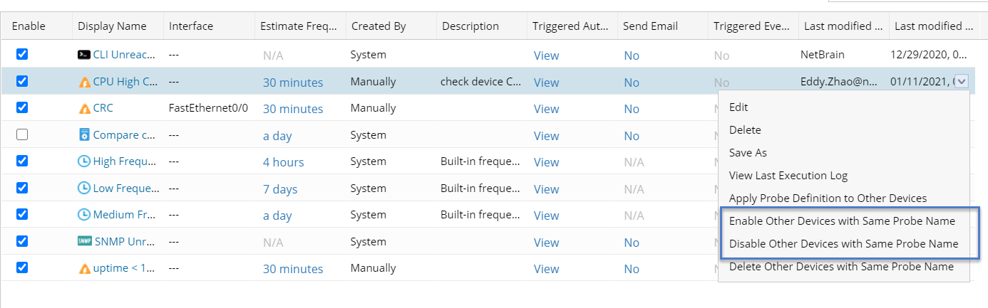
When a flash probe is enabled, it will trigger respective tasks to periodically retrieve data and perform error check. If you want to enable or disable the flash probe for multiple devices, right click a flash probe and choose from the following two options:
•Enable Other Devices with Same Probe Name
•Disable Other Devices with Same Probe Name
Adjust the Flash Probe Frequency
Once enabled, the flash probe will be executed based on the current device’s primary frequency by default. To adjust the flash probe frequency, click the frequency settings of the flash probe (top right corner as highlighted in the screenshot below), and modify the settings accordingly.

See also: