Calculate Path Across GCP Network
A GCP VPC Network consists of an IP range and subnets, and it may also contain cloud-native networking services such as GCP VPN Gateway, Cloud NAT, Cloud Router, Interconnect, and so on. NetworkBrain creates a VPC router for each VPC to simulate the routing and security check function for this VPC. The subnet is visualized in NetworkBrain's dynamic map via the concept called LAN media. From the dynamic map, you can view the different networking objects and understand how they are connected. VPC peering is also supported with the peering ID displayed on the map.

- Click Path next to the search bar.
- Enter the IP address of endpoint A in the Source field and the IP address of endpoint B in the Destination field. The available gateways are auto-identified, and you can select the desired one from the Gateway list.


|
Tip: To change the path direction, click the  icon and select the icon and select the  icon. By default, the system calculates one-way paths. icon. By default, the system calculates one-way paths.
|
- Click Path to start calculating. Then you can view the diagrammed path on the map with a detailed summary log and the related routing and security check details.

The following sections will introduce a variety of paths that can be calculated and visualized in your GCP network.
Traffic Path Across GCP and On-Premises Network
There are different ways to connect an on-premises network to a GCP VPC Network:
- VPN Gateway Connect
VPN Gateway securely connects your peer network to your Virtual Private Cloud (VPC) network through an IPsec VPN connection. Traffic traveling between the two networks is encrypted by one VPN gateway and then decrypted by the other. NetworkBrain supports visualizing the topology and path of VPN Gateway as well as the following data tables:
- Google Virtual Route Table
- Google Cloud VPN Tunnels Table
- Partner/Dedicated Interconnect
Cloud Interconnect extends your on-premises network to Google's network through a highly available, low latency connection. You can use Dedicated Interconnect to connect directly to GCP or Partner Interconnect to connect to GCP through a supported service provider. NetworkBrain supports visualizing the topology and path of Partner/Dedicated Interconnect, as well as the following data tables:
- BGP Advertised Routes Table
- Google Partner Interconnect Physical Connections Table
- Google Partner Interconnect VLAN Attachment Table
- Google Virtual Route Table
- Network Virtual Appliance (NVA)
NVA can be loaded with any vendor's virtual machine (VM) images to support networking, security, and other functions. NetworkBrain supports visualizing the topology and path of the VPN Tunnel connection between GCP NVA and on-premises edge devices.
The following diagram demonstrates the path between GCP and the on-premises network, connected by the Interconnect, VPN, and VNA.

The following diagram shows the traffic through an example of VNA, a Cisco CSR 1000v Cloud Services Router, which provides a cloud-based virtual router deployed on a virtual machine (VM) instance on x86 server hardware.

Hub-Spoke Network Path
The Hub VPC Network in GCP is a central point of connectivity to your on-premises network. The spokes VPC Network has peers with the Hub. Shared services are deployed in the Hub, while individual workloads are deployed as spokes. The following path shows that the Hub provides a shared Interconnect resource for all Spokes VPC networks to visit the on-premises devices.

VPC Network Path
You can connect VPC networks with VPC peering or a VPN connection. NetworkBrain supports visualizing the topology and path of inter and intra VPC networks, as well as the following data tables:
- Google Virtual Route Table
- Google VPC Endpoint Group Table
- Google VPC Instance Group Table
- Google VPC Instance Group Members Table
- Google VPC Peering Table
- Google VPC Routes Table
- Google VPC Subnets Table
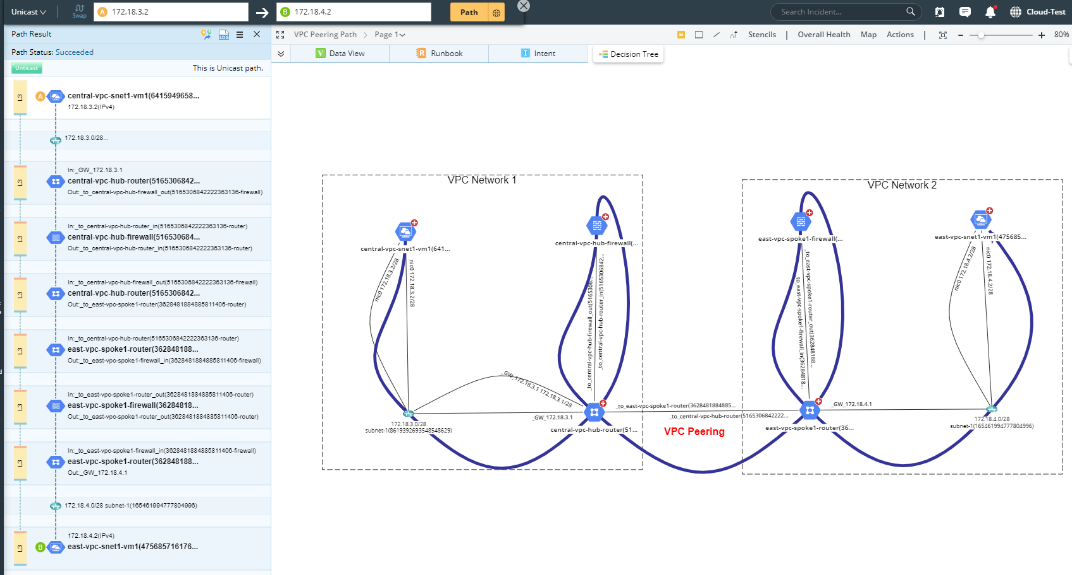
The following path demonstrates VPC network peering, which connects VPC networks so that workloads in different VPC networks can communicate internally. Thus, the traffic stays within the GCP and does not traverse the public Internet.
The following diagram demonstrates the path through an IPsec VPN connection. Traffic traveling between the two networks is encrypted by one VPN gateway and then decrypted by the other, protecting your data as it travels over the Internet.
GCP Load Balance Path
GCP Cloud Load Balancing is a fully distributed, software-defined managed service. NetworkBrain supports visualizing the topology and path of both External and Internal Load Balancer, as well as the following data tables:
- Google Load Balancer Backend Table
- Google Load Balancer Forwarding Rules Table
- Google Load Balancer Host and Path Rules Table
- Google Virtual Route Table

Shared VPC Path
GCP Shared VPC allows an organization to connect resources from multiple projects to a common Virtual Private Cloud (VPC) network to communicate with each other securely and efficiently using internal IPs from that network.

Path across Projects/Organizations
NetworkBrain supports visualizing the topology and path of the resources crossing multiple projects or organizations.
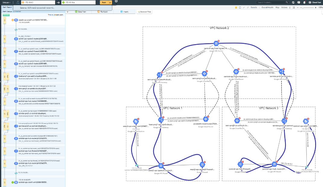
The following diagram demonstrates the path through Service Project 1 and Host Project.
The following diagram demonstrates a path crossing two organizations via VPC Peering or VPN Tunnel.

Duplicate IP Path
If multiple projects or organizations are discovered in a domain, you may have duplicated IP addresses, which can be resolved by putting them into different zones.
The following diagram shows two paths crossing different networks in the domain. Users can select different Gateways, and the system will calculate the path for different zones accordingly.
