MPLS Cloud
Generally, geographically dispersed networks are connected through the MPLS VPN network of an Internet Service Provider (ISP). The system introduces a concept called MPLS Cloud to simulate the MPLS functions by following the rules of forwarding labeled packets. In the system, an MPLS Cloud is taken as a device and uses a virtual routing table to calculate A-B paths across the MPLS.
Here is an example of MPLS VPN network, including the following types of elements:
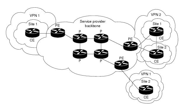
- Customer Edge (CE) — routers at the customer premises connected to the provider edge of a service provider IP/MPLS network. CE peers with the provider edge (PE) and exchanges routes with the corresponding VRF inside the provider edge (PE).
- Provider Edge (PE) — routers in the provider's network connected to the customer edge (CE) routers located at customer sites. PE routers support VPN and MPLS label functionality. Within a single VPN, pairs of PE routers are connected through a virtual tunnel, typically a label-switched path (LSP).
-
Provider (P) — provider routers within the core of the provider's network are not connected to any routers at a customer site but are part of the tunnel between pairs of PE routers. Provider routers support LSP functionality as part of the tunnel support, but do not support VPN functionality.

Note: Only the domain admin, power users, or users with the Device Management privilege can add, edit, and delete an MPLS Cloud.
Use Flow

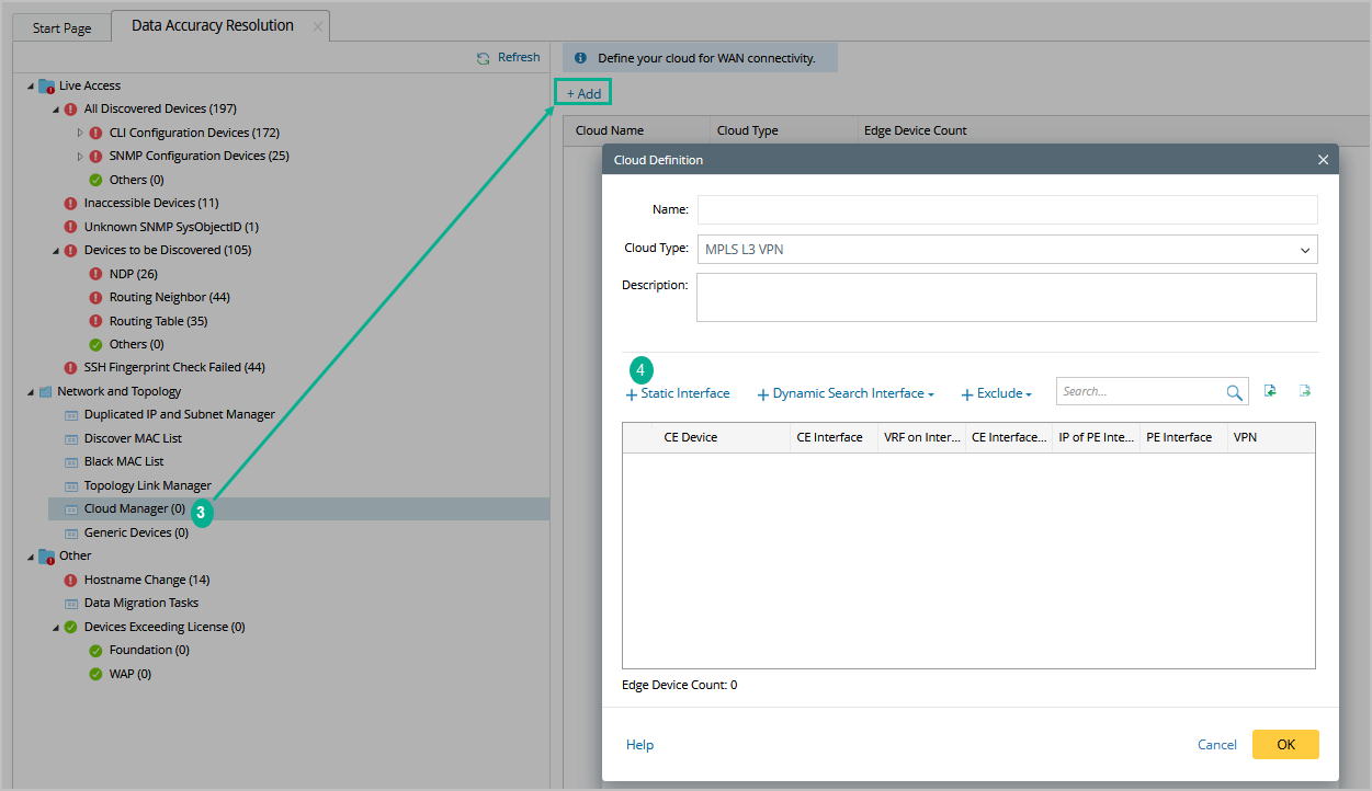
Add an MPLS Cloud
Power users can define specific clouds in their domain. After they select a cloud type, the system automatically loads the parameters defined in the cloud type.
- Log in to the Domain Management page.
-
On the Domain Management page, click Data Accuracy Resolution on the Start Page or click the start menu
 and select Data Accuracy Resolution.
-
On the Data Accuracy Resolution tab, select Cloud Manager on the left pane and click Add.
-
Follow the steps below in the Cloud Definition dialog box to define an MPLS Cloud.
- Enter a name for the cloud.
- Keep the default Cloud Type MPLS L3 VPN.
- Enter a description of the MPLS cloud.
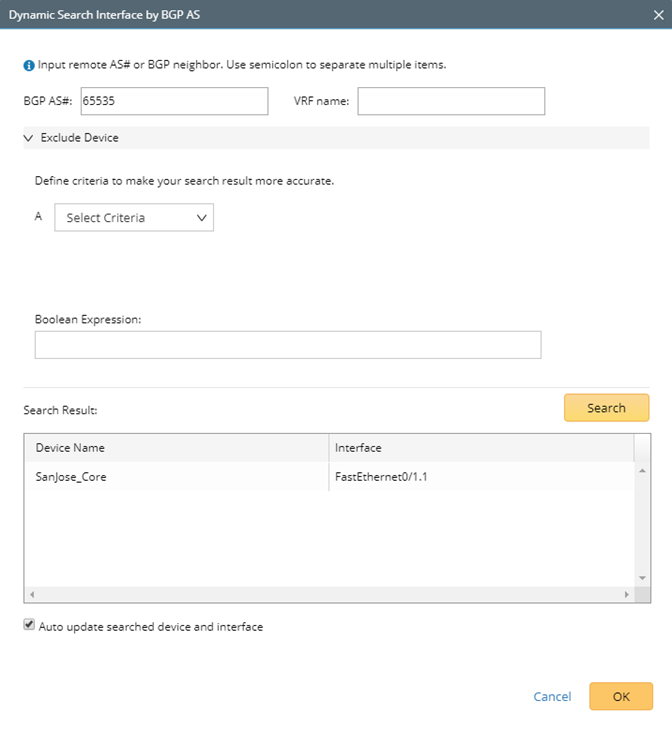
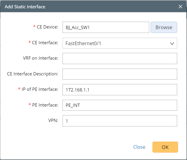
- Add MPLS edge devices to the MPLS Cloud in either of the following ways:
![]() Dynamic Search
Dynamic Search
|

- (Optional) Click Exclude to select CE devices or interfaces that you want to exclude from the MPLS cloud.
-
Click OK.
Tip: To make the MPLS cloud participate in path calculation, go to the Additional Operations after Benchmark tab to build the topology and NCT. See Benchmark Task Settings for more details.
Build Topology and NCT Table for MPLS Cloud through a Benchmark
After creating an MPLS cloud, you must build the topology and NCT table (a virtual routing table used for path calculation) via a benchmark task.
To build the topology and NCT table for an MPLS Cloud, complete the following steps:
- Log into the Domain Management page.
-
Click the start menu
 and select Schedule Task.
- Edit a benchmark task and go to the Additional Operations after Benchmark tab.
-
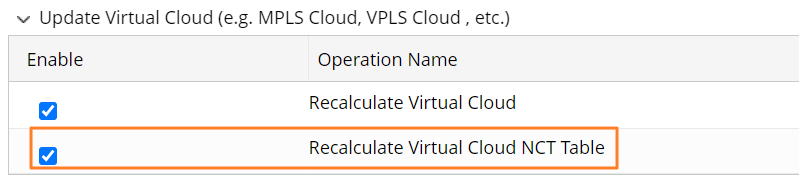
In the Update Virtual Cloud area, select the Recalculate Virtual Cloud NCT Table option.
-
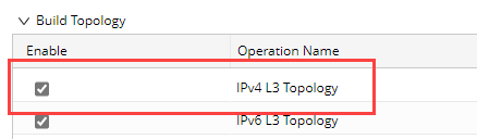
In the Build Topology area, select the IPv4 L3 topology option.
The system will build topology and NCTs for all MPLS clouds after the benchmark task is completed.
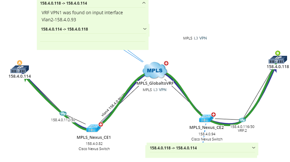
Calculate Paths across an MPLS Cloud
After building the NCT and topology, you can calculate paths across MPLS clouds. During the path calculation, the system looks up the virtual routing table to find the correct inbound and outbound traffic interfaces of the MPLS cloud.
Further operations:
![]() Exporting MPLS Cloud
Exporting MPLS Cloud
|


![]() Viewing the NCT of an MPLS Cloud
Viewing the NCT of an MPLS Cloud
|
Best Practice: