Topology Type

Contents
The following table introduces the built-in topology types.
Topology Type |
Description |
Example |
|---|---|---|
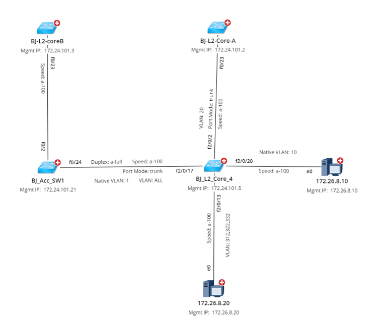
Layer 2 topology reflects the physical connections among devices. When building Layer 2 topology, the system learns how devices are connected by reading the data in NDP and MAC tables. To visualize L2 topology among devices on a map, physical interfaces and connections are parsed from device configuration files. For example, e0/0, f0/0, vlan10, and so on. Note: If the interfaces of a switch connect to multiple end systems, then a bus media will be used to connect the interface with the end system on a map. |
|
|
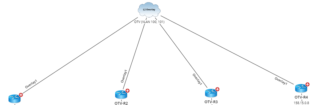
L2 Overlay Topology reflects the logical/virtual connection among devices in an L2 overlay network. When building L2 overlay topology (taking OTV for example), the system determines which devices will participate in the calculation through the GDR property “hasOTVConfig”, finds OTV interface with the same extend VLANs through the OTV.extendVLAN property and connects them to the same L2 Overlay media. |
|
|
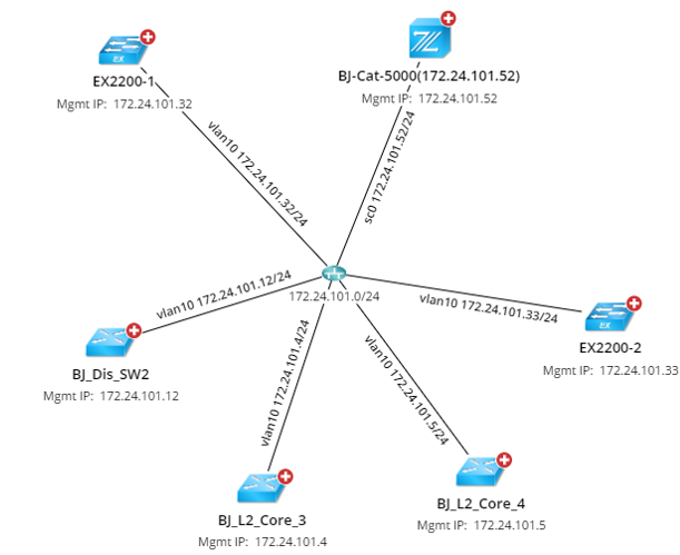
IPv4 Layer 3 topology reflects the connections among devices configured with IPv4 addresses. When building IPv4 Layer 3 topology, the system judges whether a device has IPv4 topology relationships with others by identifying whether their IPv4 addresses of interfaces are configured in the same subnet. To visualize IPv4 L3 topology among devices on a map, the IPv4 interfaces are created with the <interface name> <IPv4 address> format if the IPv4 addresses have been configured for the interfaces. For example, vlan 10 172.24.101.32/24. |
|
|
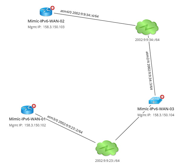
IPv6 Layer 3 topology reflects the connections among devices configured with IPv6 addresses. When building IPv6 Layer 3 topology, the system judges whether a device has IPv6 topology relationships with others by identifying whether their IPv6 addresses of interfaces are configured in the same subnet. To visualize IPv6 L3 topology among devices on a map, the IPv6 interfaces are created with the <interface name> <IPv6 address> format if the IPv6 addresses have been configured for the interfaces. For example, atm4/0 2002:9:9:34::4/64. Note: In the latest release, IPv6 Layer 3 topology only supports Cisco devices (Cisco Router, Cisco IOS Switch, Cisco IOS XR, Cisco Nexus Switch, Cisco ASA Firewall, Cisco PIX Firewall). |
|
|
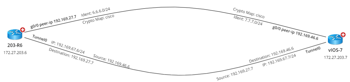
L3 VPN Tunnel |
L3 VPN Tunnel topology reflects the connections among devices configured with tunnel (GRE/IPsec VPN) technology. When building the L3 VPN Tunnel topology, the system judges whether a device has L3 VPN Tunnel topology relationships with others by identifying the tunnel peers. To visualize L3 VPN Tunnel topology among devices on a map, the VPN interfaces are created in the following formats for VPN and GRE tunnels respectively: ▪IPsec VPN Tunnel: outside peer-IP <IPv4 address>. For example, outside peer-IP 172.27.129.114. ▪GRE Tunnel: tunnel name. For example, Tunnel0. |
|
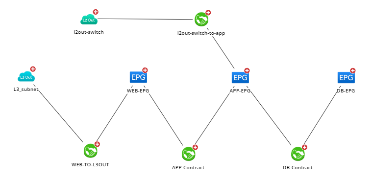
logic topology reflects the connections among network data configured with CISCO ACI and VMware vCenter technology. See Using Viusal Space to Visualize Your SDN Architecture for more details. |
|