The Basic output node provides built-in functions to analyze and display table data, such as highlight devices with particular configurations on a map, drawing devices on a map, creating an alert when a predefined condition was met, creating CSV report, and setting device properties.
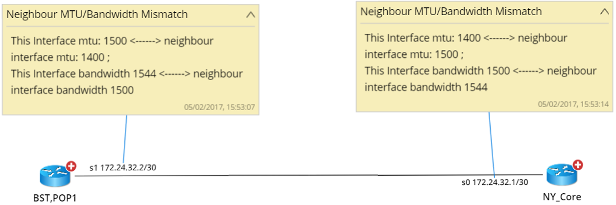
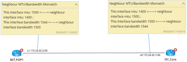
Example: Drawing notes to neighbor interfaces to show mismatched MTU
The Basic output node consists of two parts:
▪Condition — used to define conditions to trigger subsequent actions.
▪Action — used to define the actions to take when the conditions are satisfied.
Defining conditions
1.Point to the table that you want to analyze the variables.
2.Click the  icon and extend a Basic node from the table.
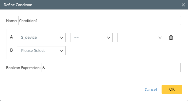
3.At the Output node, click New Condition. The Define Condition dialog opens.
Tip: The system creates a True condition by default, which means always executing the subsequent actions. If multiple conditions exist, the default condition is only executed when all other conditions are not satisfied.
1)Enter a meaningful condition name.
2)Select a variable and operator from the drop-down lists, then enter the value.
3)Repeat to add more conditions. You can use a Boolean expression to set the relationship between the added conditions, such as A and B, and A or B.
4)Click OK.

Defining actions
1.At the Basic output node, specify the execution logic to poll the table rows. The Qapp automatically selects an execution logic according to table data type by default.
▪Execute by rows — execute the basic output node by table rows. For interface-level data or multiple-instance data, this option is selected.
▪Execute once — execute the basic output only once. For single-instance data or device-level data in an attribute table, this option is selected.
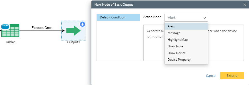
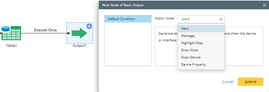
2.Select an action. Point to the Output node, click the  icon, select a condition, and select an action from the Action Node list.
Tip: You can add multiple actions in a Canvas, and these actions will be executed based on the sequence order that you add the actions.
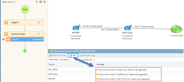
Generate alerts about a device or device interface when the device or interface metrics meet the predefined condition. There are two types of alerts:
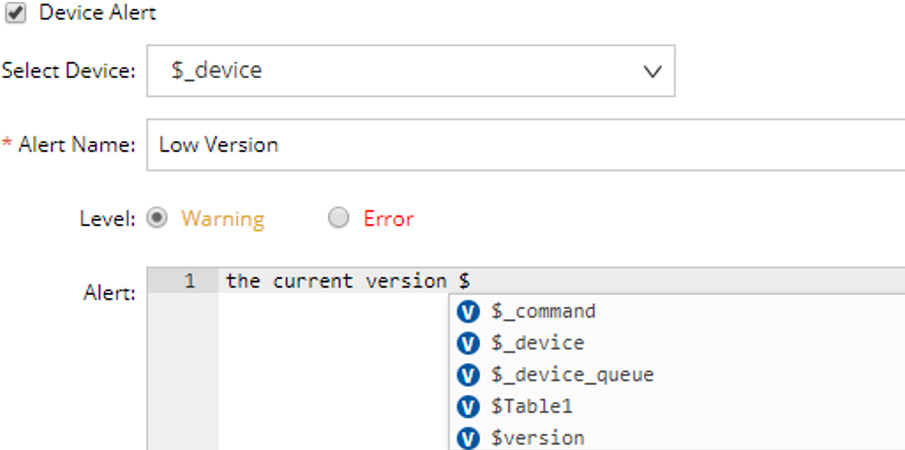
Used to define an alert about a device.
1)Select the Device Alert check box. 2)Select the device variable ($_device by default) from the Select Device drop-down menu. 3)Enter a name in the Alert Name field. 4)Select the alert level and enter the alert content in the Alert field. The alert content supports the call of variables. To call a variable, enter $ and all variables available prompt in a list.
Action Definition Sample:
 Output Result Sample:
|
Used to define alerts about device interfaces.
1)Select the Interface Alert check box. 2)Select the device variable ($_device by default) from the Select Device drop-down menu and select the interface variable. 3)Enter a name in the Alert Name field. 4)Select the alert level and enter the alert content in the Alert field. The alert content supports the call of variables. To call a variable, enter $ and all variables available prompt in a list. |
See also: Defining Alert in monitor output.
|
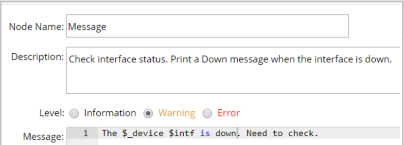
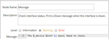
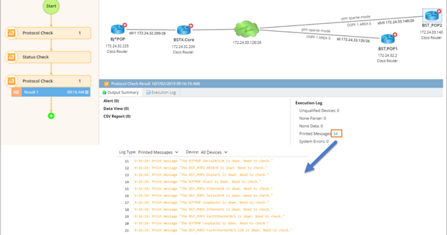
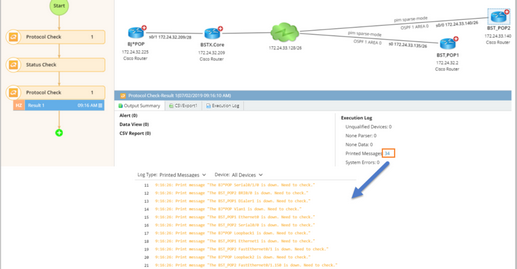
Print customized messages when the predefined conditions are met.
1)Enter a name for the Message node. By default, the name is Message1. 2)Enter a description of the node in the Description field. 3)Select the message level and enter the message in the Message field.
Message Definition Sample:
 Message Output Sample
|
Highlight devices, device interfaces or neighbor devices on a map when the predefined conditions are met.
There are three types of highlights:
Used to highlight devices on a map.
1)Check the Highlight Device check box. 2)Select the device variable ($_device by default) from the Device drop-down menu. 3)Enter a legend name for the highlight in the Legend field, such as OSPF. The legend field supports variables. Enter $ to pop up all variables available in a list.
Message Definition Sample:

Message Output Sample
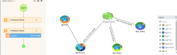 Note: The Highlight Map function only works on devices on a map, so make sure that the target devices you will highlight are on the map at runtime.
|
Used to highlight device interfaces on a map.
1)Check the Highlight Interface check box. 2)Select the device variable ($_device by default) from the Device drop-down menu. 3)Select the interface variable ($_intf by default) from the Interface drop-down menu. 4)Enter a legend name for the highlight interface in the Legend field, such as VRF. The legend field supports variables. Enter $ to pop up all variables available in a list. Note: The Highlight Map function only works on devices on a map, so make sure that the target devices you will highlight are on the map at runtime.
|
Used to highlight neighbor devices from a device on a map.
1)Check the Highlight Neighbor check box. 2)Select the source device ($_device by default) from the Source Device drop-down menu and enter the text for the link on the source device side. 3)Select the destination device (or neighbor device) from the Destination Device drop-down menu and enter the text for the link on the destination device side. 4)Enter a legend name for the highlighted neighbor in the Legend field. Note: The Highlight Map function only works on devices on a map, so make sure that the target neighbor devices you will highlight are on the map at runtime.
|
|
Generate notes attached to devices or interfaces on a map. There are three types of notes:
Used to add a note to a map.
1)Check the Map Note check box. 2)Enter a title for the note content. 3)Enter the note content in the Content field.
Note Definition Sample:

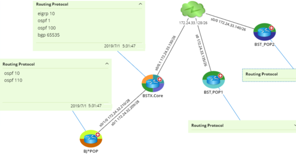
Note Output Sample:
 4)Click Advanced to configure more parameters.
|
|
|
Font Size
|
Specify the font size. The default value is 14.
|
Align
|
Specify the alignment direction. The default option is Left.
|
Forecolor
|
Specify the forecolor for the note box.
|
Background Color
|
Specify the background for the note box.
|
Border Color
|
Specify the border color for the note box.
|
Note Type
|
Specify how to display new map notes for recurring execution.
▪Append — retain the existing notes and append new notes behind. ▪Overwrite — remove the existing notes and display the new notes only. ▪History — retain the first note only (remove others) and append new notes behind. |
Note View
|
Select whether to expand or collapse the note on the map.
|
|
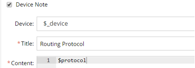
Used to draw a note attached to devices on a map.
1)Check the Device Note check box. 2)Select the device variable ($_device by default) from the Device drop-down menu. 3)Enter a title for the note content. 4)Enter the note content in the Content field. Note: The Device Note function only works on devices on a map. You can click Advanced and check the Auto Draw Device option to make sure that the target devices are on the map.
|
Used to draw a note attached to device interfaces on a map.
1.Check the Interface Note check box. 2.Select the device variable ($_device by default) from the Device drop-down menu. 3.Select the interface variable ($_intf by default) from the Interface drop-down menu. 4.Enter a title for the note content. 5.Enter the note content in the Content field. Note: The Interface Node function only works on interfaces visible on a map. You can click Advanced and check Auto Draw Interface option to make sure that the target interfaces are on the map.
|
|
Draw devices or interfaces on a map.
Used to draw a device on a map.
1)Check the Draw Device check box. 2)Select the device variable ($_device by default) from the Device drop-down menu. 3)Select a topology type based on your actual device layer. 4)Select whether to enable the auto link on the map. If enabled, two devices will be automatically linked together when they are neighbors. |
Used to draw device interfaces on a map.
1)Check the Draw Interface check box. 2)Select the device variable ($_device by default) from the Device drop-down menu. 3)Select the device variable ($_intf by default) from the Interface drop-down menu. |
Used to draw a device and its next hop.
1)Check the Draw Hop check box. 2)Select the source device ($_device by default) from the Source Device drop-down menu. 3)Select the destination device (or next-hop device) from the Destination Device drop-down menu. 4)Enter a text to be displayed on the link in the Annotation field. |
|
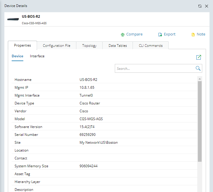
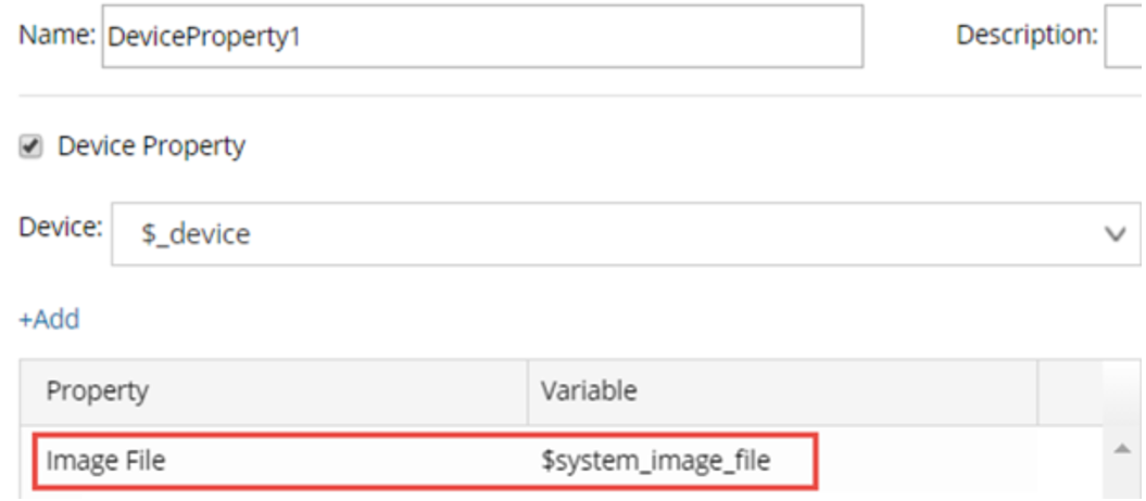
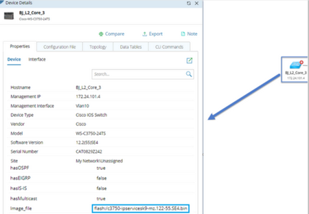
Populate the value of a device or interface property in the Device Details pane.
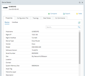
Populate device-level property value.
1)Check the Device Property check box. 2)Select the device variable ($_device by default) from the Device drop-down menu. 3)Click Add and select your interested device property
Property Definition Sample:

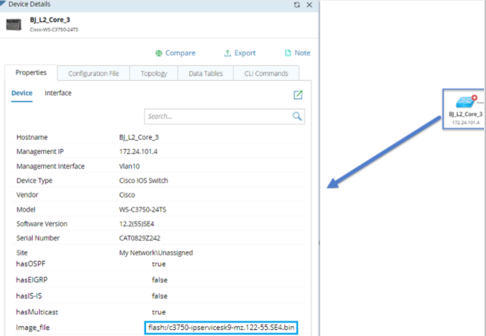
Property Output Sample:
 |
Populate interface property value.
1)Check the Device Property check box. 2)Select the device variable ($_device by default) from the Device drop-down menu. 3)Select the interface variable ($_intf by default) from the Interface drop-down menu and select the interface type. 4)Click Add and select your interested interface property. |
Populate module property value.
1)Check the Module Property check box. 2)Select the device variable ($_device by default) from the Device drop-down menu. 3)Select the module variable from the Module drop-down menu. 4)Click Add and select your interested module property. |
|
Export variables to CSV file.
Note: The CSV Export node is only available when the Basic output node follows after a Global Data Table.
Click the CSV Export node and configure the settings:
1)Select the variables that you want to export from the Export Variables drop-down menu. 2)Enter a name for the exported report file.
Report Definition Sample:
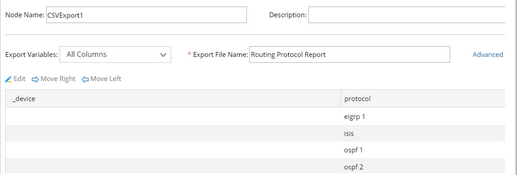 Report Output Sample:
|